Continue to Site

Eng-Tips is the largest engineering community on the Internet

Intelligent Work Forums for Engineering Professionals

  • Congratulations KootK on being selected by the Eng-Tips community for having the most helpful posts in the forums last week. Way to Go!

Another Truss Reaction Question 4

Status
Not open for further replies.

JStructsteel

Structural
Aug 22, 2002
1,352
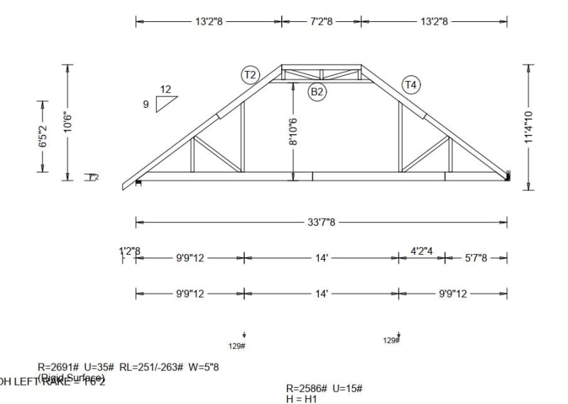
Truss reactions provided are as shown. What is the RL? I am thinking lateral, but not 100%. W=5"8 is that the bearing width?(2x6 top plate)
Capture_umb7ku.jpg
 
Replies continue below

Recommended for you

I was trying to show that the assumed lateral loads seem proportional to the projected width of the roof.

I'd minimise the assumptions and ask the guy who did the work "what the eff do your numbers mean?"

another day in paradise, or is paradise one day closer ?
 
TheRick109 said:
RL probably means "Roof Live Load"

Why would roof live load be both positive and negative?

"Reaction, Lateral" seems to make the most sens to me.
 
Guess I'm a bit late on this one.

As you already figured out, it's a horizontal reaction from a wind load case. I don't see any reason to think it's from a drag truss load.

FYI - A truss designer doesn't set up the wind load cases. We pick out the code (like IRC 2018) the MPH, and the exposure. The software sets up several wind load cases.

And I can tell you from experience they don't really effect the design of the trusses themselves very much. It might add CLBs in the webs of really long trusses. In very tall, steep pitched trusses it might possibly change a plate size. But not often.

Mainly it produced an uplift value on the truss drawings. We send a packet of truss drawings to jobsites with every load. Which the framer promptly throws in the trash.

In cases where tie-downs are installed, they're rarely installed correctly. So to me it's largely a waste of time to have wind loads. I realize things might be different in areas where they have building codes and inspections. But not where I work.
 
Ron - here in (or rather on the edge of) hurricane country, we take those things a bit more seriously. If an inspector walks on a job site with trusses and the truss package isn't there, he'll shut them down until they get them with the approved permit set (and they'd better have a permit approval stamp on them, too). Permits aren't approved without finalized truss packages. Further south they're even more strict (and rightfully so).

The hurricane ties are another story. I agree they are often installed incorrectly - either the clip itself or the load path. Everyone loves to install them on the interior, but have no additional hardware. If the truss span is less than about 24' that might still be okay for some of the building, but not typically at the corners. And even if they put them on the outside, nobody really understands what is required to call the sheathing an uplift load path...especially if it's doing double duty as a shear/braced wall.

 
Another thing I have noticed, and Ron correct me if I'm wrong, is that truss software doesn't typically account for actual wind zones rather the whole truss is designed for a zone, ie Zone 3 is typically a small L shape in the corner, but the whole truss may be designed for that, so IMO many uplift reactions are conservative.
 
phamENG - I totally get that in hurricane country things are and should be different.

Although even there I wonder. I've read reports of inspections of houses after hurricanes. Some of the reports said the roof sheathing was only held on by 2 nails per truss. Shingles only had 2 staples in them. Plates only had bolts in them every 40' or so. (All of this is going from memory, so it may not be 100% accurate)

Designing the trusses for wind won't help if you can't keep the plywood on the roof.


Aesur -

I can't speak for all designers. Our software has an option to "design all trusses for end zones". I keep that checked all the time. And I teach newbies to do it that way.

Even at that - If our gravity loads are 50# (30 PSF live and 10 PSF dead) - Wind loads may only be a fraction of that. So if doesn't affect the design of the truss much.
 
Redneck Ron said:
Even at that - If our gravity loads are 50# (30 PSF live and 10 PSF dead) - Wind loads may only be a fraction of that. So if doesn't affect the design of the truss much.

...except for the 0.6DL + W load case
 
I agree that wind rarely controls strength of members and usually has more to do with connections and load paths. Once you use that 1.6 duration factor, even really large wind loads begin to look a bit like regular live loads.

And yes, lots of buildings are poorly built. Most of those reports are likely about houses that got ripped apart. Those aren't the sort that I design. Robust load paths are the name of the game.
 
The last mystery number, like 5"8 is 5 inches and 8 sixteenths.
The number is how many 1/16 of an inch. So 3/4 inch would be 12 for example.

That is how prefab wood truss manuf. do their shop dwgs.

Also, there should be no horizontal reaction. You need to call your truss shop and tell them to design the
truss with one end as a roller. They have basically modeled it incorrectly, which means that truss design is not
how reality is going to work.

We do this because it is near impossible to resist horizontal force from a truss with a tall spindle of a wall or column.
You cannot do it. The wall will bow out, the bottom chord will go into tension....

Prefab wood truss designers, despite good intent, are sort of a dangerous group. They know just enough to get themselves into
a real bind....like the guy who did your truss without rollers. They think they are engineers, but are not. I'm not saying
this to offend anyone. It is the truth.

We review their work closely for this purpose.
 
bigmig said:
Also, there should be no horizontal reaction. You need to call your truss shop and tell them to design the
truss with one end as a roller.
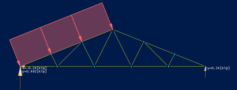
There has to be a horizontal reaction, otherwise the roof would slide off the walls whenever it was windy. If you have a pin and roller, the pin will pick up the entire horizontal reaction.

Pin_Roller_hucwlt.png
 
CrabbyT said:
If you have a pin and roller, the pin will pick up the entire horizontal reaction.

Actually, the roof diaphragm picks it up but how to model that? I suppose pretending you have a pin at the bearing is fine for most analyses until the software gets more sophisticated.
 
XR - true, but it's nice to have it dumped in one spot for easy review. You can take that number, add the wall pressure to it, and verify the diaphragm loading from the original design.
 
@CrabbyT I see your logic, but XR250 is correct. The roof acts as a diaphgram and transfers lateral load to the shearwalls. That is
why the roof does not slide off during a wind event. The shearwalls hold it in place so long as there is an adequate drag strut connection
between the roof and the wall.


XR250 said:
Actually, the roof diaphragm picks it up

Since it's a flexible diaphragm, is it valid to assume that the wind would only get transferred to the (2) exterior side walls? Wouldn't the lateral force get transferred to the wall that the trusses are pinned to? My understanding of diaphragms wasn't that that directed the load to the outside of the building so much as they distributed lateral forces to the elements in proportion to the relative stiffness of those elements. I would contend that the side walls would have a lot more stiffness than the walls perpendicular to the force, but in my mind, it seems unconservative to neglect the lateral force acting on the perpendicular wall.

What I'm saying is, why not design the perpendicular wall to take up the lateral reaction of each truss, and why not design the side walls to half the total lateral reaction of the entire roof?

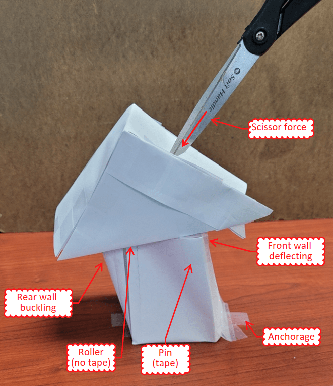
I just did a desktop experiment by making a house with paper walls and a paper roof. The roof has 3 "trusses" (they're actually just triangles) and a diaphragm. If I push on the center of the roof (directly on the center truss truss), the side walls take up enough force to cause the rear wall to buckle, but the front wall still deflects.

paper_house_bvdeyn.png
 
CrabbyT - in a hyper realistic sense, sure, it'll transfer to elements based on their relative stiffness. But in light frame wood construction, who has time to design like that? It's a flexible diaphragm, for distribution to shear walls assume the diaphragm has zero stiffness and the load is distributed based on tributary area alone. Then look at diaphragm as a structural element with reactions at those locations to determine shear in the diaphragm. But the lateral load is taken by the diaphragm to the shear walls - often the exterior walls.

Your model is neat, but the scale and materials make it invalid. The paper lacks the ability to simulate wood framing, and the proportions of your little house don't match the reality of any building I've ever designed.

All of that said, a positive connection of the roof truss to the wall is important. It should be fixed to prevent lateral displacement at both ends. The 'roller' effect comes not from actually releasing the truss reaction, but from the lack of lateral resistance/stiffness in the wall that is pinned at the foundation and pinned at the truss. The reaction shown on that truss diaphragm is more about the load delivered to the LFRS and not the load delivered to the wall. The wall delivers load to the truss on its way to the diaphragm.

 
phamENG said:
The 'roller' effect comes not from actually releasing the truss reaction, but from the lack of lateral resistance/stiffness in the wall that is pinned at the foundation and pinned at the truss. The reaction shown on that truss diaphragm is more about the load delivered to the LFRS and not the load delivered to the wall. The wall delivers load to the truss on its way to the diaphragm.

This makes sense. It's like designing a 100' long steel box truss supported by towers. You put a 4-legged tower (a pin) at one end and a 2-legged tower (a roller) at the other.

In case someone Googles this thread in the future (and for the embiggenment of my own knowledge)... For the purposes of designing shear walls (let's imagine the 2 exterior side walls for simplicity), would the following equation give the total force on one of the shear walls?

F[sub]shear[/sub] = [RL * (n[sub]trusses[/sub] - 1)] / 2

w[tt][/tt]here RL = the lateral truss reaction and n[sub]trusses[/sub] is the number of trusses? Subtract one truss because the end trusses only have half the tributary area of the other trusses.
 
Only from the roof. You still have to add in the shear from the wall that's connected to the truss. Load path is wall->truss/blocking->diaphragm->shear wall->foundation.

And I'd probably go with F[sub]shear(roof)[/sub]=(RL/s)*L/2 where s is the truss spacing and L is the length of the roof. Should be the same result, but it fits my thought process a little better.
 
Status
Not open for further replies.

Part and Inventory Search

Sponsor