All,
I'm now patent pending on my design updates incorporated since filing the original patent, so I can show it now and solicit critique (for those familiar with the system engineering process, the first patent reflected Preliminary Design while the new continuation patent reflects down select of mechanization options to a final design). There are still a number of details to complete, but I estimate final design is about 90% complete at this point.
Folks may recall my engine is a rotating cylinder radial that uses opposed pistons mated to a dedicated charge pump for scavenge/charge and employs a two-stroke Homogeneous Charge Compression Ignition (HCCI) cycle. All pistons are driven by cams, and each set of cylinders completes four full cycles per revolution. With six cylinder sets, the result is 24 complete cycles per revolution. One key difference between the current design and the original is the relocation of the charge pump from its radial position coaxial with the opposed pistons to a new position beside the opposed pistons. This change allows use of a third cam to drive the charge pump piston which previously moved in unison with the outside piston of the opposed pair. This new position shortens the transfer passage between the charge piston and the opposed pair, allows greater flexibility in charge pump timing versus the opposed pair, eliminates the cam shaft (and associated flexure) of the prior design, and maximizes the cam contact area of the heavily loaded pistons of the opposed pair. Combined with a new intake/exhaust port layout, the new approach significantly reduces back pressure (and thus pumping loss) during scavenge/charge. Another key change in the new design is reduction of the innermost piston's stroke to encompass opening and closing the intake port alone while allocating the full compression/expansion stroke to the outer piston of the pair. This change is a simple matter of mechanics; the radius of the inside cam is much smaller than the radius of the outside cam, and the larger radius cams can move further in a given number of degrees and a given material stress limit. The final major difference in the new design is the incorporation of a traditional valve/port controlled version of the Atkinson cycle to mechanize variable compression ratio and control autoignition timing; the inner cam controlling intake port timing is rotated relative to the outer cams so the port remains open during some portion of the compression stroke (note the charge pump cam profile is the inverse of the main piston's cam profile during this period so the net pressure of the Atkinson transfer is near zero). This facility is controlled according to knock sensors in the inner cam as well as atmospheric pressure and temperature sensors to vary compression and ensure ignition occurs at the ideal time in the cycle.
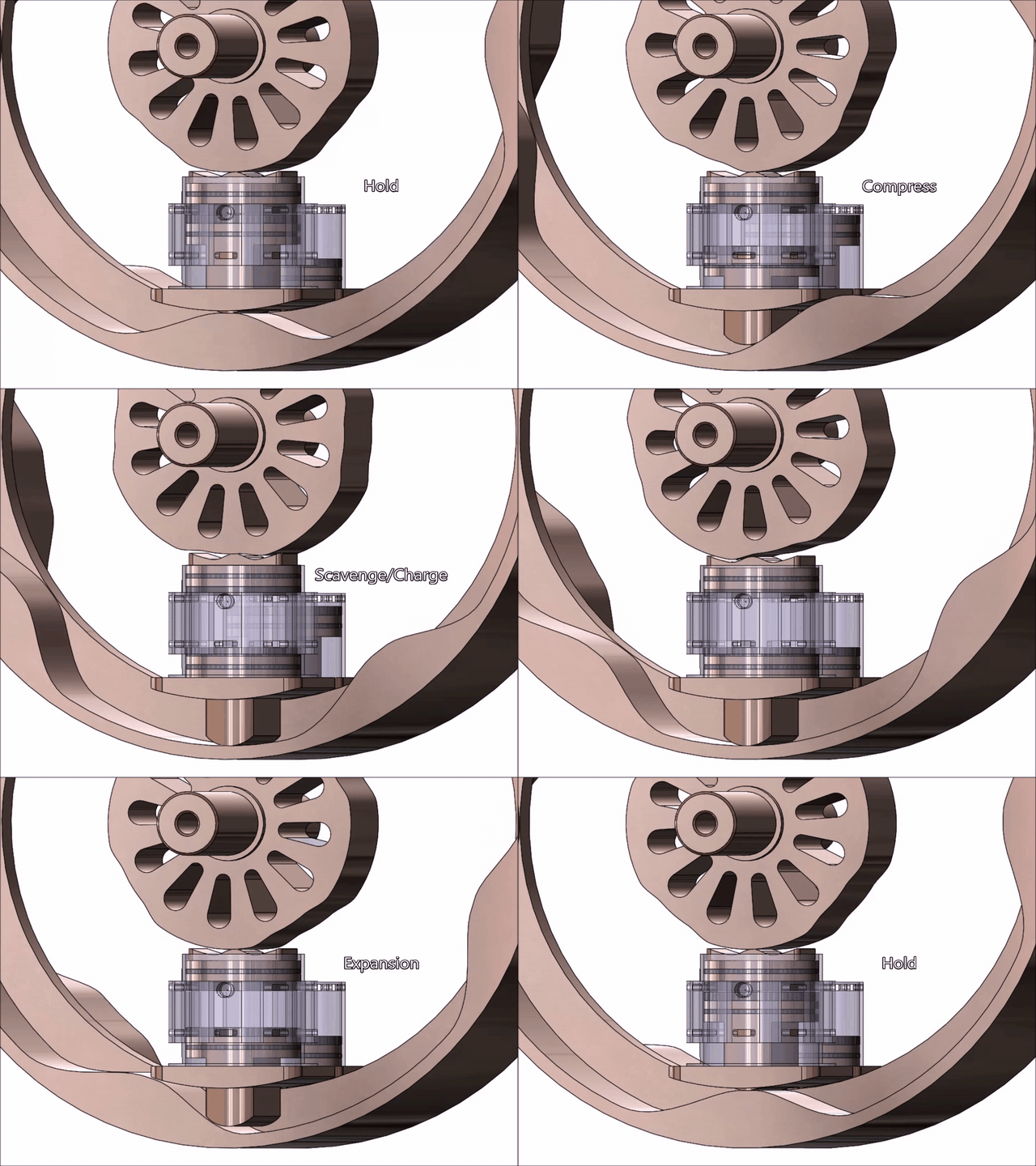
Below is a Solidworks Motion Study animation of one cylinder set (of 6) comprised of an opposed piston pair and a charge pump piston. Note that the animation rotates the cams rather than the pistons and cylinders as in the final design so that the cycle can be better observed. The animation shows the charge pump ports are aligned with the intake ports which are open and closed by the upper (or innermost) piston. Note the circular pocket near the intake ports in the main cylinder; this is where the fuel injectors are installed. Driven by a cam in the side housing, these fuel injectors start injecting at a fixed point in the cycle representing the latest possible closure of the intake port.

Per my math and CAD models, the prototype engine will displace between 25 and 31 cc depending on altitude and ambient conditions (25cc on a standard day at sea level). The engine will be 6 inches in diameter and 5 inches thick and employ a bore of just over 1 inch with stroke sweeping a total of 0.481 inches (including the 0.062 inch tall ports at the top and bottom of the cylinder). It will produce 5.7 HP @ 2,626 RPM (propeller speed) and 11.5 lb-ft of torque with 58.6% efficiency including friction and pumping loss (68.3% theoretical) at sea level. 73% of said performance will be available at 15,000 foot altitude (even though air density is only 62.9% of that at sea level). The weight is high at 16.5 lb, but I expect that to come down to around 10-12 lb after weight reduction is complete (deferred until after all other aspects are proven). Performance figures are, of course, subject to validation in real hardware, but I'm encouraged by the 58.6% efficiency indicated by the models; as long as the end result is above 50%, I've got a real product.
Based on threads regarding the Achates engine, I imagine some will be quick to point out that opposed piston engines tend to dump oil out the cylinder ports. Now that the updated patent is filed I can say that this is one area where a rotating cylinder block is key; the passages to and from the intake and exhaust ports will be tilted slightly inward toward the motor axis such that oil exiting the ports can be collected via centrifugal force and routed back into the low pressure oil loop (which flows nearby through passages surrounding each cylinder for cooling). This of course assumes that the oil exiting the ports is in liquid form, and I'll have to conduct experiments to determine how it exits the port and how best to capture it aided by centrifugal force.
The whole point of this post is to solicit constructive criticism, so don't hold back. I only ask that it be constructive and respectful.
Rod
I'm now patent pending on my design updates incorporated since filing the original patent, so I can show it now and solicit critique (for those familiar with the system engineering process, the first patent reflected Preliminary Design while the new continuation patent reflects down select of mechanization options to a final design). There are still a number of details to complete, but I estimate final design is about 90% complete at this point.
Folks may recall my engine is a rotating cylinder radial that uses opposed pistons mated to a dedicated charge pump for scavenge/charge and employs a two-stroke Homogeneous Charge Compression Ignition (HCCI) cycle. All pistons are driven by cams, and each set of cylinders completes four full cycles per revolution. With six cylinder sets, the result is 24 complete cycles per revolution. One key difference between the current design and the original is the relocation of the charge pump from its radial position coaxial with the opposed pistons to a new position beside the opposed pistons. This change allows use of a third cam to drive the charge pump piston which previously moved in unison with the outside piston of the opposed pair. This new position shortens the transfer passage between the charge piston and the opposed pair, allows greater flexibility in charge pump timing versus the opposed pair, eliminates the cam shaft (and associated flexure) of the prior design, and maximizes the cam contact area of the heavily loaded pistons of the opposed pair. Combined with a new intake/exhaust port layout, the new approach significantly reduces back pressure (and thus pumping loss) during scavenge/charge. Another key change in the new design is reduction of the innermost piston's stroke to encompass opening and closing the intake port alone while allocating the full compression/expansion stroke to the outer piston of the pair. This change is a simple matter of mechanics; the radius of the inside cam is much smaller than the radius of the outside cam, and the larger radius cams can move further in a given number of degrees and a given material stress limit. The final major difference in the new design is the incorporation of a traditional valve/port controlled version of the Atkinson cycle to mechanize variable compression ratio and control autoignition timing; the inner cam controlling intake port timing is rotated relative to the outer cams so the port remains open during some portion of the compression stroke (note the charge pump cam profile is the inverse of the main piston's cam profile during this period so the net pressure of the Atkinson transfer is near zero). This facility is controlled according to knock sensors in the inner cam as well as atmospheric pressure and temperature sensors to vary compression and ensure ignition occurs at the ideal time in the cycle.
Below is a Solidworks Motion Study animation of one cylinder set (of 6) comprised of an opposed piston pair and a charge pump piston. Note that the animation rotates the cams rather than the pistons and cylinders as in the final design so that the cycle can be better observed. The animation shows the charge pump ports are aligned with the intake ports which are open and closed by the upper (or innermost) piston. Note the circular pocket near the intake ports in the main cylinder; this is where the fuel injectors are installed. Driven by a cam in the side housing, these fuel injectors start injecting at a fixed point in the cycle representing the latest possible closure of the intake port.

Per my math and CAD models, the prototype engine will displace between 25 and 31 cc depending on altitude and ambient conditions (25cc on a standard day at sea level). The engine will be 6 inches in diameter and 5 inches thick and employ a bore of just over 1 inch with stroke sweeping a total of 0.481 inches (including the 0.062 inch tall ports at the top and bottom of the cylinder). It will produce 5.7 HP @ 2,626 RPM (propeller speed) and 11.5 lb-ft of torque with 58.6% efficiency including friction and pumping loss (68.3% theoretical) at sea level. 73% of said performance will be available at 15,000 foot altitude (even though air density is only 62.9% of that at sea level). The weight is high at 16.5 lb, but I expect that to come down to around 10-12 lb after weight reduction is complete (deferred until after all other aspects are proven). Performance figures are, of course, subject to validation in real hardware, but I'm encouraged by the 58.6% efficiency indicated by the models; as long as the end result is above 50%, I've got a real product.
Based on threads regarding the Achates engine, I imagine some will be quick to point out that opposed piston engines tend to dump oil out the cylinder ports. Now that the updated patent is filed I can say that this is one area where a rotating cylinder block is key; the passages to and from the intake and exhaust ports will be tilted slightly inward toward the motor axis such that oil exiting the ports can be collected via centrifugal force and routed back into the low pressure oil loop (which flows nearby through passages surrounding each cylinder for cooling). This of course assumes that the oil exiting the ports is in liquid form, and I'll have to conduct experiments to determine how it exits the port and how best to capture it aided by centrifugal force.
The whole point of this post is to solicit constructive criticism, so don't hold back. I only ask that it be constructive and respectful.
Rod

