Continue to Site

Eng-Tips is the largest engineering community on the Internet

Intelligent Work Forums for Engineering Professionals

  • Congratulations SDETERS on being selected by the Eng-Tips community for having the most helpful posts in the forums last week. Way to Go!

Any constructive criticism of my updated design approach? 4

Status
Not open for further replies.

RodRico

Automotive
Apr 25, 2016
508
All,

I'm now patent pending on my design updates incorporated since filing the original patent, so I can show it now and solicit critique (for those familiar with the system engineering process, the first patent reflected Preliminary Design while the new continuation patent reflects down select of mechanization options to a final design). There are still a number of details to complete, but I estimate final design is about 90% complete at this point.

Folks may recall my engine is a rotating cylinder radial that uses opposed pistons mated to a dedicated charge pump for scavenge/charge and employs a two-stroke Homogeneous Charge Compression Ignition (HCCI) cycle. All pistons are driven by cams, and each set of cylinders completes four full cycles per revolution. With six cylinder sets, the result is 24 complete cycles per revolution. One key difference between the current design and the original is the relocation of the charge pump from its radial position coaxial with the opposed pistons to a new position beside the opposed pistons. This change allows use of a third cam to drive the charge pump piston which previously moved in unison with the outside piston of the opposed pair. This new position shortens the transfer passage between the charge piston and the opposed pair, allows greater flexibility in charge pump timing versus the opposed pair, eliminates the cam shaft (and associated flexure) of the prior design, and maximizes the cam contact area of the heavily loaded pistons of the opposed pair. Combined with a new intake/exhaust port layout, the new approach significantly reduces back pressure (and thus pumping loss) during scavenge/charge. Another key change in the new design is reduction of the innermost piston's stroke to encompass opening and closing the intake port alone while allocating the full compression/expansion stroke to the outer piston of the pair. This change is a simple matter of mechanics; the radius of the inside cam is much smaller than the radius of the outside cam, and the larger radius cams can move further in a given number of degrees and a given material stress limit. The final major difference in the new design is the incorporation of a traditional valve/port controlled version of the Atkinson cycle to mechanize variable compression ratio and control autoignition timing; the inner cam controlling intake port timing is rotated relative to the outer cams so the port remains open during some portion of the compression stroke (note the charge pump cam profile is the inverse of the main piston's cam profile during this period so the net pressure of the Atkinson transfer is near zero). This facility is controlled according to knock sensors in the inner cam as well as atmospheric pressure and temperature sensors to vary compression and ensure ignition occurs at the ideal time in the cycle.

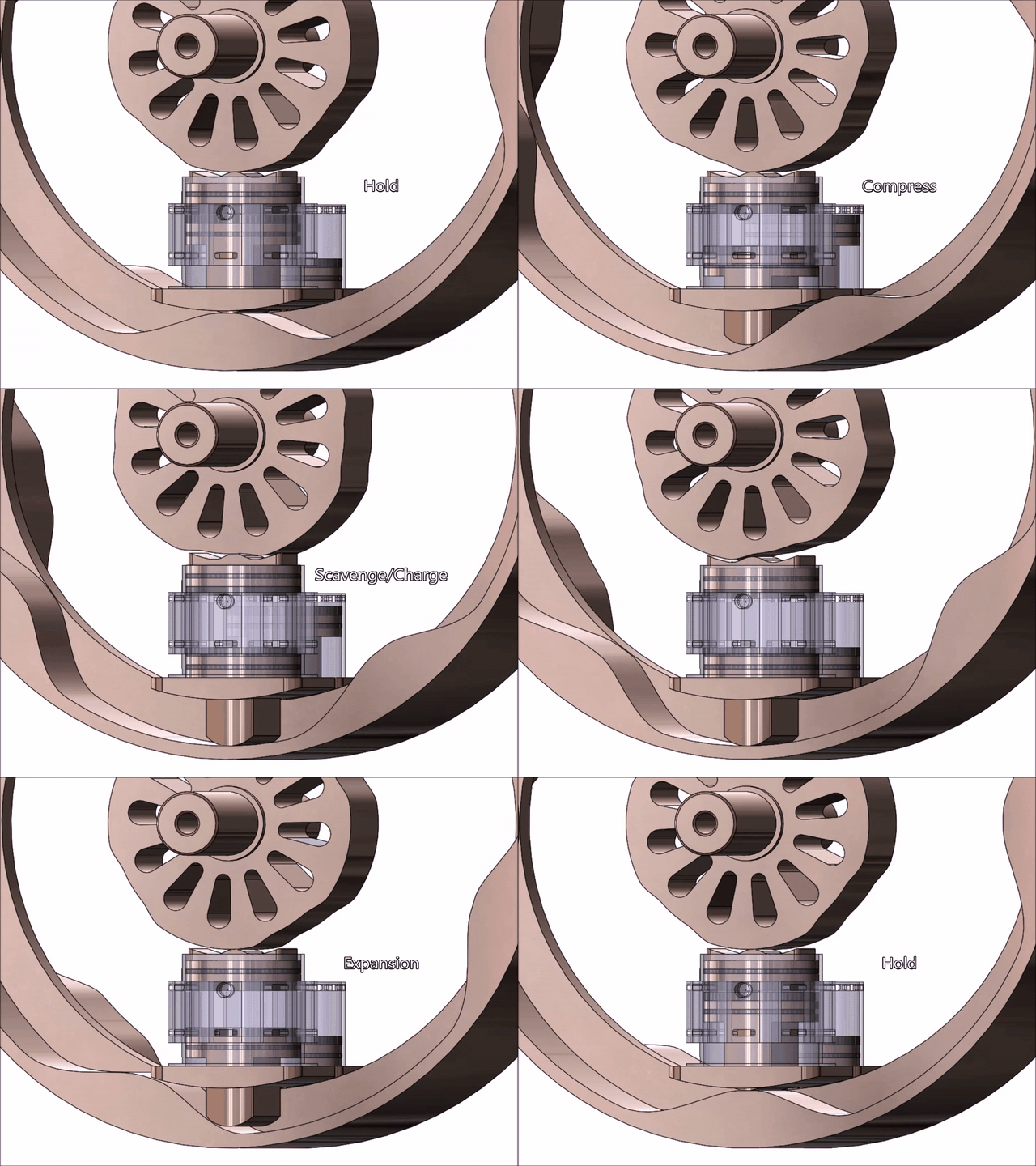
Below is a Solidworks Motion Study animation of one cylinder set (of 6) comprised of an opposed piston pair and a charge pump piston. Note that the animation rotates the cams rather than the pistons and cylinders as in the final design so that the cycle can be better observed. The animation shows the charge pump ports are aligned with the intake ports which are open and closed by the upper (or innermost) piston. Note the circular pocket near the intake ports in the main cylinder; this is where the fuel injectors are installed. Driven by a cam in the side housing, these fuel injectors start injecting at a fixed point in the cycle representing the latest possible closure of the intake port.
Annotated-Long_vgttyt.gif


Per my math and CAD models, the prototype engine will displace between 25 and 31 cc depending on altitude and ambient conditions (25cc on a standard day at sea level). The engine will be 6 inches in diameter and 5 inches thick and employ a bore of just over 1 inch with stroke sweeping a total of 0.481 inches (including the 0.062 inch tall ports at the top and bottom of the cylinder). It will produce 5.7 HP @ 2,626 RPM (propeller speed) and 11.5 lb-ft of torque with 58.6% efficiency including friction and pumping loss (68.3% theoretical) at sea level. 73% of said performance will be available at 15,000 foot altitude (even though air density is only 62.9% of that at sea level). The weight is high at 16.5 lb, but I expect that to come down to around 10-12 lb after weight reduction is complete (deferred until after all other aspects are proven). Performance figures are, of course, subject to validation in real hardware, but I'm encouraged by the 58.6% efficiency indicated by the models; as long as the end result is above 50%, I've got a real product.

Based on threads regarding the Achates engine, I imagine some will be quick to point out that opposed piston engines tend to dump oil out the cylinder ports. Now that the updated patent is filed I can say that this is one area where a rotating cylinder block is key; the passages to and from the intake and exhaust ports will be tilted slightly inward toward the motor axis such that oil exiting the ports can be collected via centrifugal force and routed back into the low pressure oil loop (which flows nearby through passages surrounding each cylinder for cooling). This of course assumes that the oil exiting the ports is in liquid form, and I'll have to conduct experiments to determine how it exits the port and how best to capture it aided by centrifugal force.

The whole point of this post is to solicit constructive criticism, so don't hold back. I only ask that it be constructive and respectful.

Rod
 
Replies continue below

Recommended for you

OK, this is the first time I've understood the engine in this long discussion, I guess I'm your visual learner.

Looking at it, I wonder what keeps the pistons from getting cocked and jamming. Which is to say that you've got a moment on the piston which is L*P(time)* piston area(µ + tan(angle of the cam surface)) where L is approx. the distance from the piston ring to the contact point on the cam and P(time) is the pressure at any point in time. Have you looked into this?

Edit: I see the guide now.

I'm still not clear what spins here, the part with the pistons or the cam. Either way, I see the cam vibrating if not well supported.
 
I imagine you need a breather on the guide plate and you'll have an associated pumping loss.
 
Moon161,

The odd shape of the inner piston near the inner cam provides a flat surface for transfer of side thrust resulting from cam interaction. The outer piston of the opposed pair and the charge pump piston both have guides as you note in your edit. Your point about needing to vent the guides under the pistons with the long strokes is a good one (thanks!). I'll explore adding holes to the guides or putting another ring of ports around the bottom of those two cylinders for venting. Adding another ring of ports will likely yield the least pumping resistance. I'll have to see if I can route them to the intake channels somehow so I can reuse the intake air filter. Good catch. I can't believe I missed it. That's a good example of the value f peer review!

The cylinder block rotates counterclockwise from the pilot's perspective (per convention) and the cams are stationary. The use of a rotating cylinder block (aka a rotor) facilitates incorporation of a low pressure centrifugal oil pump used for lubrication and cooling as well as the method used to recover oil scraped into the ports.

If I had shown all cylinders operating in the animation, it would be clear that there is always a cylinder set on the opposite side of the rotor that's in precisely the same portion of the cycle. This results in near perfect balance with direct and reaction loads cancelling at the bearings. As for vibration, I believe it will be driven primarily by the firing pattern. If you label the six cylinders North (N), North East (NE), South East (SE), South (S), South West (SW), and North West (NW), the firing pattern is N and S, NE and SW, SE and NW. As each opposing pair fires, it tries to squish the inner cam and stretch the outer cam ever so slightly (making both a bit oval). Fortunately, the outer cam is thickest where the combustion pressure is greatest, and that's where it's attached to the side housings, so there's very little actual movement. Nonetheless, I think the engine will have a characteristic tone at 4x the RPM. I wish I had the processing horsepower to simulate the engine in operation, but I don't; it will have to wait for prototype test.

Rod
 
Also, is it OK for the pistons to float? I don't see any elements that will keep the pistons on the cam except for charge & combustion pressure.
 
Rod,

A couple questions, first, what is forcing the inner pistons to be in contact with and follow the cam? Are there bias/return springs somewhere that aren't shown?

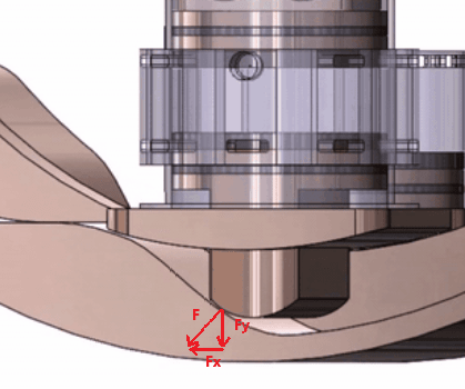
Second, in the below screen grab of your animation it looks like the interface angle between the piston and the cam face on the power stroke is around 45 degrees, meaning that the force rotating the pistons relative to the cam (Fx in the picture) is only about 70% of F neglecting losses to friction. This would seem to hurt your efficiency and create a lot of wear as the piston tries to dig into the cam, how was this angle chosen?

Untitled_dr7j5x.png
 
moon161,

Included in the last 10% of design is the addition of springs. I have the requirements based on the sum of acceleration, gas pressure, and centrifugal force, but haven't yet decided what kind of spring to use. Flat springs are simplest but compression springs are more efficient and don't wear. Just another design decision to work through.

Rod
 
hendersdc,

Per my above response to moon161, I'm currently in the process of selecting springs. I have all the forces (requirements), I just haven't decided on which spring to use or how to incorporate them. I don't anticipate problems in this area, but I'm always ready to be surprised at how a minor challenge can become a major challenge (it happens more often than I like to admit).

The maximum pressure angle of the cam you've chosen to illustrate is actually 38.01 degrees (the max pressure angle of the inner cam is 22.12 degrees, and that of the charge pump is 41.82 degrees). Similar to a crankshaft, only a portion of the vertical force applied to the cam is transferred to rotational force. The rest remains unexpended in the combustion gas as potential work (this is why crankshafts are more efficient than some assume based purely on angles). The cam and follower are designed to handle the full maximum force applied at a zero degree pressure angle (unexpected premature detonation) with 100% margin, so there's little or no risk of plastic deformation. Because of the radius of the cam, the surface speeds are high (1509 fpm min, 7927 fpm max), and they combine with the surface width, hardness (aged Maraging 350 steel with 56 Rc), and micro-polished finish to keep the assembly in the hydrodynamic regime at all times. Note, by the way, that there's a 0.039 in fillet on the follower edges that's not shown (I accidentally left them suppressed when I ran the animation).

As for how the contact angles were chosen, I knew I wanted them as large as possible during expansion (not because they're more mechanically efficient but because they reduce the time available for heat transfer and ring blow-by) but also have to keep an eye on acceleration, jerk, and yield margin. I thus created a math model in Excel that calculates total force (acceleration, centrifugal, gas) and yield margin then increased the pressure angle to the maximum possible within the limits dictated by the need to accelerate/decelerate smoothly with minimum jerk while staying withing the stress limits.

The cams are both the boon and the ban of my design. On the plus side, they allow precise control of timing and thus facilitate HCCI. On the down side, they are finicky compared to crankshafts. More time has gone into the cams than any other aspect of the design (with fuel injectors coming in second), and I have a lot of experiments and measurements planned during the prototyping phase. If I succeed, it will be because of the cams. If I fail, it will be because of the cams.

Rod


I have never seen any evidence to suggest that cam actuation (ie unusual velocity profiles) is advantageous to initiating HCCI.

je suis charlie
 
I see a mechanism that is rather large relative to the swept volume, allowing for 6 of the piston sets as mentioned.
I don't know much about cams but I'd be interested in the comments of anyone involved in the successful design and release of a camshaft for an engine for commercial application. Particularly concerning the mechanical efficiency, and durability.

"Schiefgehen wird, was schiefgehen kann" - das Murphygesetz
 
Gruntguru,

If you had heard of cam based HCCI using my approach, it would be patented, and my first patent would not have been allowed.

Companies working HCCI seek to incorporate HCCI into standard engines. That doesn’t work well for a variety of reasons. To date I believe only Mazda is committed, and their spark assisted HCCI is not standard HCCI.

My engine consultant worked on several HCCI teams at large auto companies. He was excited after his review of my design and singled out the cams as a new approach worth pursuing because they allow better contol of timing wgich is critical from the perspective of the chemical kinetics. You literally could not attain the timing I’m using with a crankshaft.

Do you any other aspects on you’d like to offer constructive input?

Rod
 
I would suggest some fundamental research on HCCI and dV(olume)/dt profiles. At the very least a single cylinder version of your design.

You may think my criticisms are non-constructive, but my intention is to help you save a lot of money and time.

je suis charlie
 
gruntguru, I have done extensive research into HCCI, and I hired a consultant experienced in HCCI to review my calculations and design. I plan a large number of what we used to call in the defense R&D biz "critical experiments." Every aspect of the engine will be tested and refined in isolation before a complete engine is built. Rod
 
hemi,

hemi said:
I see a mechanism that is rather large relative to the swept volume, allowing for 6 of the piston sets as mentioned.

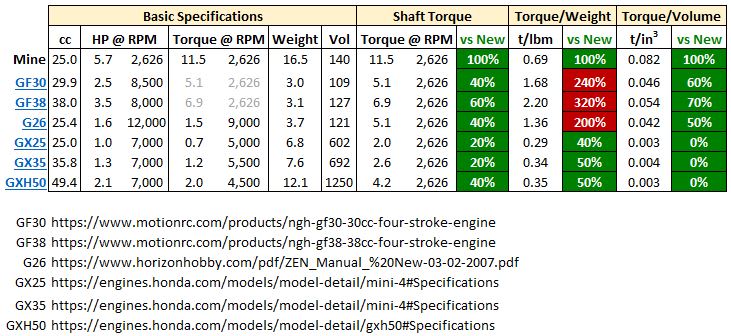
I think you're questioning power density. Below is snapshot of the comparison of my engine to several competing engines. My engine is summarized at top. The GF30, GF38, and G26 are popular engines used in giant-scale model aircraft. The GX25, GX35, and GXH50 are Honda utility engines. I use torque as the basis for comparison reflecting application driving constant speed propellers. Since most competing engines run at high RPM compared to mine, I grant them use of a lossless reduction gear and calculate their torque at 2,626 RPM. Looking at torque alone, the closest competitor has only 60% of my torque. Comparing torque/weight, the model aircraft engines kick my tail but the Honda utility engines aren't even close (note I expect to bring the weight of my engine down substantially by removing unnecessary metal, but I won't put any significant effort into that task until everything is working). Comparing torque/volume, mine wins (this is the basis for my belief mine can be made significantly lighter).

Capture_ek86ne.jpg


hemi said:
I don't know much about cams but I'd be interested in the comments of anyone involved in the successful design and release of a camshaft for an engine for commercial application. Particularly concerning the mechanical efficiency, and durability.

You're intimately familiar with cams that operate reliably for 100's of thousands of miles. You could imagine my engine using stationary cylinders with the pistons driven by cams on rotating shafts connected by gears. The challenge is friction, and that depends on lubrication. The average outside radius of my outside cam is 2.87 inches and the radius of the follower is .325 inches. Just like a journal bearing, the rotating outer cam is pulling oil under the cam/follower interface. The effectiveness of such bearings is determined by surface speed, interface length, and material hardness. My surface speed is very high (1509 fpm min, 7927 fpm max) as is my hardness (aged Maraging 350 steel with 56 Rc), and the length is substantial (0.989 inches). The trick will be maintaining the proper amount of oil on the cam, and that's a non-trivial challenge. At present, I'm planning to felt wipe the cam surface with oil, but I can't vouch for the efficacy of this approach until I get through the associated critical experiments.

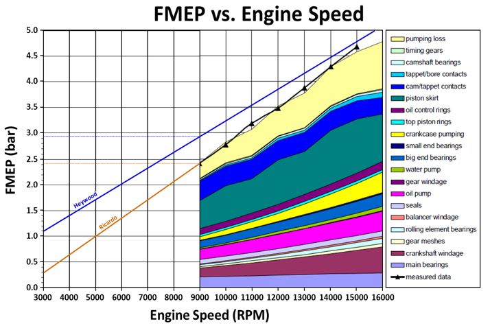
As it stands, my analysis includes the friction of an automotive valve train (the comparison is apt given my "valve" lift is only 0.418 inches and my "valve" mass is only 0.083 lb). Below is a plot of friction losses (Friction Mean Effective Power aka FMEP) by subsystem from Ricardo with a blue line showing total friction according to Heywood. I average the two to estimate FMEP in my analysis. The estimate is, of course, only approximate, so I have to refine it during critical experiments. My plan is to put a heavy spring between the pistons and spin the rotor using an electric motor to estimate friction while measuring motoring torque.

Capture_ghozjz.jpg
 
Neither torque nor BMEP is a good basis for comparing different engine types targeting the same application unless they happen to have the same output rpm at their respective design points.
You can't use FMEP from a conventional reciprocating engine as an estimate for your FMEP. Nor can you use the [conventional engine's] valvetrain contribution to relative or absolute friction, since the power being dissipated in the valvetrain is but a fraction of the shaft power. You could use the average torque required by a reciprocating engine's valvetrain divided by a summation of the average normal force on the cam lobes as an indicator for the friction torque of your cam system per unit of the summed average normal force. How good of an indicator probably depends on many factors, but it's a starting point.

"Schiefgehen wird, was schiefgehen kann" - das Murphygesetz
 
hemi said:
Neither torque nor BMEP is not a good basis for comparing different engine types targeting the same application unless they happen to have the same output rpm at their respective design points

I agree it would be unfair to compare engines designed to operate at different RPMs without gearing them to the application. That's why I granted each engine a "free" (zero size and weight, 100% efficient) transmission to multiply their peak torque (the greater of their stated torque@RPM or their HP*5252/@RPM) and reduce their shaft speed to the common RPM of 2,626.

hemi said:
You can't use FMEP from a conventional reciprocating engine as an estimate for your FMEP

I disagree. It's a reasonable approximation useful until motoring FMEP can be better approximated on a dyno.

hemi said:
Nor can you use the [conventional engine's] valvetrain contribution to relative or absolute friction

I don't use the valvetrain number in isolation. I use the average of the full FMEP described by Heywood's and Ricardo's trendlines of full-engine FMEP over RPM. Of course it's not exact, but the similarity between Heywood's and Ricardo's results indicates there is reasonable correlation of FMEP and RPM. On the plus side, I used the entire estimate including all the components and subsystems that aren't present in my engine.

The fact is, I won't know IMEP, BMEP, FMEP, torque, HP, or efficiency until I test the full engine. My math models only provide approximations to guide design decisions, and I see no alternative to use of informed approximations at this phase in the process. I do plan critical experiments specifically targeting FMEP using a motoring dyno. Even those measurements will be approximations, they'll just be better approximations. The only real measures of performance will be torque, RPM, fuel consumption, and emissions of a full engine running under load.

 
Your piston that operates the piston port (transfer port) needs to close off those ports far enough that the (presumable) piston rings on that piston cover the ports, not just the top of the piston. It'll leak like crazy if only the piston crown (and not the rings) cover the ports.

And on a related note ... Having that piston just cover the ports, while its opposing piston does a full stroke, is thermodynamically identical to having both pistons do a half-stroke and having the combustion chamber in the middle of the cylinder as opposed to at one end with the intake ports barely covered. The thermodynamic cycle only cares that the specified volume (compression) is achieved - it doesn't care how or where. Increasing the stroke of your intake-port-operation piston while reducing the stroke of your main power and exhaust port piston changes nothing in terms of complexity, changes nothing in the thermodyanmics, and will make sure the intake ports are actually covered by the piston rings, and will allow the pressure angle of your power-piston cam-follower against its cam to be made shallower.

I don't see what's driving your intake-port piston to actually go outward and stay in contact with its cam ... especially if you have the cylinder block spinning and the cams stationary. Centrifugal action will drive that piston outward (covering the ports and out of contact with the piston).

Personally? I think FMEP is going to be killer, except maaaaaaybe if all cams have rollerized followers. And if the FMEP isn't killer, leakdown will be. And if that's not killer, heat transfer will be (cylinders too small).

I don't see the advantage of using the cam-follower strategy as opposed to a crank-driven strategy with a roots blower (see Commer Knocker, or Fairbanks-Morse).
 
BrianPeterson said:
Your piston that operates the piston port (transfer port) needs to close off those ports far enough that the (presumable) piston rings on that piston cover the ports, not just the top of the piston.
It does cover the port. I'm using a Dykes top ring with the top of the ring level with the crown.

BrianPeterson said:
Having that piston just cover the ports, while its opposing piston does a full stroke, is thermodynamically identical to having both pistons do a half-stroke and having the combustion chamber in the middle of the cylinder as opposed to at one end with the intake ports barely covered. The thermodynamic cycle only cares that the specified volume (compression) is achieved - it doesn't care how or where. Increasing the stroke of your intake-port-operation piston while reducing the stroke of your main power and exhaust port piston changes nothing in terms of complexity, changes nothing in the thermodyanmics, and will make sure the intake ports are actually covered by the piston rings, and will allow the pressure angle of your power-piston cam-follower against its cam to be made shallower.
I originally split the stroke between the inner and outer pistons for the reason you describe. When designing the cam profiles, however, I realised (and observed in results) that the smaller base diameter of the inner cam compared to the outer cam means that a given change in displacement results in a proportionally smaller radius of curvature and that means its stress is higher for a given contact force. As it stands, the inner and outer cams have nearly identical stress margin. Also note I inject fuel from the side at an angle down into the cylinder volume. The injector outlet is just below the intake ports and is slanted down the longest distance to the opposing wall. If I split the stroke between the two pistons, I have to move the injector outlet further down the cylinder wall and have to spray at a shallower angle (the extreme case being a straight shot at the opposing wall). I beleive the slanted spray will have less wall impingement and will yield a better mix.

BrianPeterson said:
I don't see what's driving your intake-port piston to actually go outward and stay in contact with its cam ... especially if you have the cylinder block spinning and the cams stationary. Centrifugal action will drive that piston outward (covering the ports and out of contact with the piston).
Correct. I've already responded to prior comments on the matter explaining that I'm in the process of adding springs to all pistons. Likely flat springs for the inner most piston and compression springs for the others.

BrianPeterson said:
I think FMEP is going to be killer, except maaaaaaybe if all cams have rollerized followers. And if the FMEP isn't killer, leakdown will be. And if that's not killer, heat transfer will be (cylinders too small).
I can't use roller cams; the combination of peak load and surface speeds are too demanding. Not sure why you think leakdown will be a killer. Heat transfer is incorporated in my models and shows I'm losing 213K during expansion from 2150K to 663K. That seems reasonable relative to published papers, and my consultant said it looks about right based on his experience as well.

BrianPeterson said:
I don't see the advantage of using the cam-follower strategy as opposed to a crank-driven strategy with a roots blower (see Commer Knocker, or Fairbanks-Morse).
The cam approach is much smaller than a design using crankshafts, crankshafts don't provide fine control of timing like a cam, and they can't produce four full cycles per revolution. I acknowledge the cams are one of the largest (if not the largest) risk element, and I plan a number of critical experiments focusing on their performance. I'm surprised, however, that you view a cam turning at 2,626 RPM max moving a 0.083 lb piston 0.418 inches over a 20 degree period is neigh onto impossible. Finally, a roots blower would be terribly inefficient compared to my charge pumps (which operate at maximum back pressure of only 0.1 bar).
 
Rodrico said:
agree it would be unfair to compare engines designed to operate at different RPMs without gearing them to the application. That's why I granted each engine a "free" (zero size and weight, 100% efficient) transmission to multiply their peak torque (the greater of their stated torque@RPM or their HP*5252/@RPM) and reduce their shaft speed to the common RPM of 2,626.
Ok, I follow your method now, but it is obscure and needlessly complicated. Engines for the same or similar applications are normally compared via either BMEP or power density (displacement or mass basis). Comparing engines intended for dissimilar applications usually doesn't get you very far due to all the dissimilarities. By dissimilar I also mean physical size of the target application (e.g. toy model airplane vs large scale drone).

"Schiefgehen wird, was schiefgehen kann" - das Murphygesetz
 
RodRico said:
gruntguru, I have done extensive research into HCCI
Fundamental research or literature review? What I had in mind - specifically - was a test rig that establishes the benefit or otherwise of novel piston actuation in achieving the elusive goal of stable HCCI over a wide operating range.

My concern is that you are investing a lot of time and effort in detail design prior to any single-cylinder testing of the underlying concept which is critical to success of the entire design.

je suis charlie
 
Status
Not open for further replies.

Part and Inventory Search

Sponsor