Eng-Tips is the largest engineering community on the Internet

Intelligent Work Forums for Engineering Professionals

  • Congratulations waross on being selected by the Tek-Tips community for having the most helpful posts in the forums last week. Way to Go!

AS3600-2018, CL14.5.4 and 'closed fitments' 1

Status
Not open for further replies.

Gishin1

Structural
Jun 24, 2019
38
0
0
AU
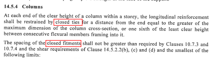
The 2018 code now states that ANY wall 65MPa or great must comply with Section 14.5.4 regardless (refer 11.7.4 & 14.6.3). 14.5.4 states that any (wall) with N*> 0.65x0.3f'c must have each longitudinal bar restrained by a "closed fitment".

Firstly, what denotes a closed fitment?
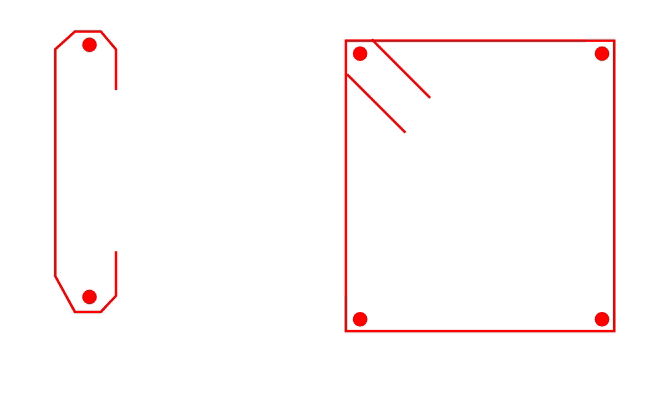
I have always thought that 'closed' referred to a fully enclosed shape detail with typically two 135 corner hooks. Section 14.5.4 refers to 'closed ties' and 'closed fitments', both of which have separate definitions in Section 1.

Section 14.6.2.2 refers to 'closed stirrups', which isn't explicitly defined in Section 1, and Figure 14.6.2.2 shows what I typically think of as a closed fitment/tie/stirrup/ligature.

Section 14.6.2.3 refers to 'closed fitments' but Figure 14.6.2.3 draws single leg ties with 135 degree hooks at either end. Figure 14.6.2.3 also refers to them as ligatures/ties.

My point to all this is that 14.5.4 is very onerous for 65MPa or greater walls with N*>0.2f'c. Whether a 65MPa wall is designed for ductility or not, CL14.5.4 still applies.

Secondly, if a wall requires a lot of steel for tension, that's a lot of bars that need to be restrained. Is the only real option here to have an inner layer of 'tension bars' and an outer layer of restrained bars confined in the core to avoid having to tie every single bar, if the bars are only in two layers?

Thirdly, is a single leg tie with two 135degree hooks considered a 'closed tie'?
If the ties have to be as per Figure 14.6.2.2, this is extremely onerous on site for the steel fixers. Figure 14.6.2.3 is not as taxing, but still not as convenient as the internal ties shown in section 10.


It seems to me that this all might be too onerous, given that a slender 50MPa wall or blade column can be designed to section 11 without any moment magnification or confinement. That's a huge jump in detailing requirements from a 50MPa wall to 65MPa. I understand the changes are to combat 200x1000 65MPa 'walls' and the like, but engineers can still detail 200x1000 50MPa 'walls' with little consequence.

I feel like high strength walls have been hit hard or standard strength walls not hard enough, as mid strength slender walls can still be exploited through section 11's very generous capacities compared to section 10.

Be keen to get some opinions on this?
 
Replies continue below

Recommended for you

Had not noticed that, but interestingly, the person in charge of drafting the rules in 8.3.3 is also the person in charge of drafting the rules on strut-tie!

He should have known better as it was he who wanted tie used only for strut-tie!
 
I've read through the draft for the 2nd Amendment of AS3600-2018 but could not find any clarification on which 'closed tie' the code committee is trying to specify. Even in Clause 14.6.2.3 they specify closed ligatures but in Figure 14.6.2.3 they show what is defined as closed ties.

Is the consensus that a single leg with 135 degree hooks on both ends can provide adequate core confinement to walls with >=65MPa concrete? Or would we need to specify closed ligs everywhere?

Capture3_h38lvc.png
 
I'm having a similar debate with my colleagues.

I have 65MPa core walls, so I'm being referred to 14.5.4.

But the same clause refers to both 'ties' and fitments'.

I don't understand if I'm allowed to use open (C-shape) ligs or not? I really don't want to show fully closed (O-shaped) ligs everywhere.

image_p1fsrp.png
 
A Tie is defined as a single leg with 135 degree hooks on the ends.

A fitment is one or more units of reinforcement developed with 135 degree hooks on the ends.

One of or a group of "units of reinforcement" of which Ties are a type make up a Fitment.

So in 14.5.4 its use is interesting. The first "closed ties" being plural is a Closed Fitment. So technically correct both ways, but I agree the first would be better as Closed Fitment.

Second is correct.

As you move down the clause,

(b) should possibly be "fitment bars" as a fitment is made up of bars.

The sentence after (d) should probably be Fitment, not Tie.

The next sentence is probably correct at "fitments" if it is talking about the total wall/column, or "Fitment" if it is talking about each set.

The last sentence should probably be Tie as it is talking about restraining an individual bar, but could also be Fitment as a Fitment can consist of a single unit.

But in any case, they all need 135 degree hooks if f'c > 65MPa.

And alternate 90 and 135 degree hooks if f'c <= 65MPa. But if you use this detail, consecutive "ties" on a longitudinal bar must have 90 and 135 degree hooks, so you have to make sure the installer alternates the 90 degree and 135 degree ends over the length of the bar. Good luck with that on site and in checking it with the forms in place! I would be using 135 degree everywhere.

Semantics aside, does it really matter what we call them!
 
Hi rapt,

thanks for your prompt response.

in summary, do you think we can use the open C ligs or do we need to have it fully closed?

if it's the latter, can we use 2x C-ligs to close the loop?

sorry for the additional questions, i'm still confused.

regards,
winston
 
Hi all,

I feel like we are leaning towards using open ligs rather than fully closed ligs. Given the ambiguity of the new code, can we even justify using open ligs? Is there a process we can go through to quickly clarify these requirements?

Given that this is a new requirement, I've not personally come across a situation like this in the past.

Cheers!
 
I think the conclusion is that single leg fitments, with 135 hooks on both ends is compliant with 14.5.4.

Rapt,
The internal ties detail from section 10 (single leg with one hooked end, one cogged) is very commonly seen in wall designs to the old code. Steel fixers are very familiar with this detail and don't often get it wrong, and if they do, it's an easy fix. Form boxes for walls generally have one side open for easy inspections. The great thing about this detail is the install is very manageable for the fixers on site, and if they make a mistake, it's very easy to rectify.

Section 10 still allows this detail for 65MPa columns, if N*<0.3Agf'c. So low stressed 65MPa walls designed as columns could still technically get away with the detail?. Any 65MPa wall above 30% stress needs double booked fitments.

I do think it's a shame the hooked&cogged detail is being done away with, given it's practicality on site, and the number of existing structures with them. Perhaps it could still be used in section 14.5.4 but with more stringent spacing requirements?
 
Winburg22

Does your open C leg have hooks at one or both the ends of the legs? If not, I don't think that detail would have ever been acceptable, new or old code.
 
Look at clause 10.7.4.2 text and the Fig 10.7.4.2.

A C leg with 2 135 degree bends is closed. With 2 90 degree bends is presumably "open" and not allowed. There is a dispensation to allow alternate 90/135 bends for f'c <= 65MPa.

Gishin1,
Obviously your company checks the installation on its own designs and presumably gets the designer to do it. Not all companies are so conscientious and often the site inspections are done by someone who could not make it as a design engineer or is a draftsperson and does not understand some of the subtleties.

But do they alternate the hooked/cogged ends so that every second tie on a longitudinal bar is 135 degree? You cannot have consecutive 90 degree bends on the same bar, or 90 degree bends on side by side longitudinal bars at the same level. They have to alternate vertically and horizontally! Most steel fixers I have seen in operation would not like that requirement.

It is not being done away with. Until 2009 (from memory) it was not allowed. It was included in 2009 based on ACI at the request of the reinforcing industry, but should have been limited to <= 70MPa also in accordance with ACI but someone missed that one. We are now in accordance with ACI at > 65Mpa in 10.7.4.2.

I think if we had followed NZS, it would be done away with for all cases (Agent666 can confirm).
 
Hi Gishin, thank you for your response. What is the justification behind single leg ties with hooks on both ends being compliant with 14.5.4? It's still unclear as the code references both closed ties and closed fitments within that clause.

I believe Winston's case is similar to the first image I posted before with hooks at both ends.
 
16.2.3 specifically says for Boundary elements detailed in accordance with 10.7.4, of which 10.7.4.2 is obviously a part and gives the rules on column "Ties/Fitments".

14.5.4 is not quite as specific as it references 10.7.3 and 10.7.4 for the amount of ties required but does not specifically mention detailing of the ties/fitments except that it has the 65Mpa rule requiring closed fitments (a tie with 2 135 degree bends is CLOSED according to the definitions). I will get that confirmed but it would appear logical that it is also controlled by 10.7.4.2.
 
HD-111,

If you read back through this post, specifically at Rapt's comments, you'll find the justification. Figure 14.6.2.3 also makes this clear.
My main take from this is that a single leg tie is acceptable if both ends are hooked, and therefore anchored into the core of the wall. A 90 degree cog doesn't work as the cover concrete is blown off at ULS. 3600 has always noted this in the beam shear section as well.

 
Rapt,

Yes, I generally prefer to do my own inspections, but I have always specified on the drawings that the cog/hook ties be alternated vertically and horizontally, even before the 2018 code explicitly stated it. I thought it was fairly obvious, but, you know... I've generally had no issues getting this done on site either. I've had the luxury of meeting the same steel fixers on multiple projects, so they generally know what I expect.

I agree that the detail should be limited to 65MPa max, but the 2018 edition also states that N*<0.3f'c. Given that columns typically have about 0.4-0.5f'c capacity, this detail probably won't be used much any more in columns. CL11 walls typically have approx 0.33f'c capacity, so if you comply with CL11 capacity, you probably wouldn't be specifying ties anyway (at least for <=50MPa).
And if your wall goes above CL11 capacity, the wall is above 0.3f'c, so you couldn't make use of the detail..there would be a very small window of walls that could make use of the detail.
 
Gishin1

ACI also requires the .3f'c Ag limit for column ties rule relaxation!

It also shows a separate pretty picture for boundary elements with alternate 90/135 degree cog/hook ties.

Interestingly, ACI also uses the term "Closed Tie" but does not appear to define it at all! It does not use "Fitment", it uses "Hoops" which are defined as a group of closed ties with seismic hooks (a 135 degree bend). And then allows the relaxation of the seismic hook requirement as we have in AS3600 for f'c < 70 and N* < .3f'c Ag.

Hope all of the USA engineers have been able to understand its version with limited definitions supplied!
 
ACI generally refers to single leg ties as crossties, regardless of the end conditions. I like this terminology and think it would be good to adapt.

Additionally, the 70MPa/0.3f'c limit is within the earthquake resistant structures section of the code, not in general requirements for columns (as per 3600). It also explicitly states that the this is only a requirement if displacements beyond the elastic range occur. i.e. Mu>1.

In AS3600, this rule applies to all columns (and walls designed as columns) regardless.

Furthermore, ACI also explicitly states that out of plane moments in walls are to be magnified, and have explicit limits of the simplified wall capacity. The simplified approach cannot be used so easily, and slenderness can't be ignored.

Unfortunately, AS3600 does not have this, therefore, the answer to the newer AS3600 restrictions is just to stick with 50MPa walls, and do away with moment magnification and confinement reinforcement - which I don't agree with - but is very much possible AND occuring.

Again, I'm not trying to get out of the rigorous detailing, and I think it's a necessity. But the jump in detailing requirements from 50MPa to 65MPa in 3600-2018 is huge, and feels like it has been implemented into 3600 CL14 without much thought or consideration to other parts of the code. And this is why there appears to be disconnect between section 10, 11 & 14.
 
ACI does not have special tie requirements for f'c > 50Mpa either! They do not recognise the need for better restraint design as the concrete becomes more brittle. Maybe they will catch up to us soon.

The alternate to a alternating 135 and 90 degree ends was all 135 as per the 2001 code for all concrete strengths.

The wall confinement problem has been addressed in the next amendment. It is getting too complicated!

We tried to limit the simplified wall rules more for earthquake but it was a step too far for some. Section 11 simplified method is only allowed for non-ductile walls in 14.4.4. Forcing 2 layers of reinforcement for compression over 3MPa was supposed to further limit its use for "bad" walls. Plus slenderness is improved by requiring 2 layers of reinforcement.
 
Status
Not open for further replies.
Back
Top