Continue to Site

Eng-Tips is the largest engineering community on the Internet

Intelligent Work Forums for Engineering Professionals

  • Congratulations SSS148 on being selected by the Eng-Tips community for having the most helpful posts in the forums last week. Way to Go!

ASCE Wind Loads on Rooftop Round Ductwork 1

Status
Not open for further replies.

Boiler106

Structural
May 9, 2014
211

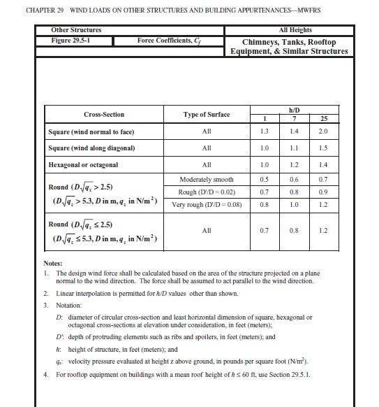
Trying to decide on my wind loading for a long stretch of horizontal 28 inch diameter round ductwork located on a 35 ft tall roof, 3' off the roof top.

Using ASCE 7-10, rooftop structures wind pressure (eq 29.4-2) = qh x GCr where GCr does not account for the circular shape.

Does it make sense to apply this pressure to the ductwork, alone? Or could i apply the round shape Cf factor on top of the rooftop equipment pressures?

Im also open to using methods in asce 7-16.

 
Replies continue below

Recommended for you

ASCE 7 16 said:
30.10 ROOFTOP STRUCTURES AND EQUIPMENT
FOR BUILDINGS
The C&C pressure on each wall of the rooftop structure shall
be equal to the lateral force determined in accordance with
Section 29.4.1 divided by the respective wall surface area of
the rooftop structure and shall be considered to act inward and
outward. The C&C pressure on the roof shall be equal to the
vertical uplift force determined in accordance with Section 29.4.1
divided by the horizontal projected area of the roof of the rooftop
structure and shall be considered to act in the upward direction.

In Chapter 29.4.1 There are equations to get the force, and references to get the Cf factor for round surfaces.

That aught to do it. Also just a note, Wind analysis is quite complicated, but I'd be willing to bet if you came up with pressure from both methods they would be reasonably close and both end up with a similar design results. I try not to get too hung up on getting exactly correct results for wind.
 
well, no, the two pressures are very different from one another even before multiplying by the force coefficient for a round object, stemming from the 1.9 GCr factor for rooftop equipment.

29.5 allows for Cf force coefficients for structures greater than 60 ft, but in 29.5.1, it is omitted.

 
Well it seems you have to use equation 29.4-2 then. I don't really see any other options then?
 
Something seems off here, but I haven't researched in detail.
Specifically, chimneys tanks, signs, frames and towers on a roof fall under one section (29.4) while rooftop structures and equipment fall under a different section (29.4.1) with completely different loading- although the physical difference between the two might be negligible. So if your 28" cylinder is a duct, it's one paragraph, but if it's a tank, it's the other, even if shape is identical. Am I missing something?

Also, I note in the Commentary on C29.4.1, "The resulting loads are expected to be overly conservative if applied to linelike structures", but doesn't say what to do about it (if anything), either.
 
JStephen - the big difference is that the chimneys, tanks, towers, etc. tend to extend vertically well above the roof plane while rooftop structures are a bit more "squat". By extending well above the roof plane, they move out of turbulence that develops as the wind breaks over the edge of the roof. The lower stuff is right in that turbulent, sped-up air and is exposed to greater loading.

Screenshot_2022-06-23_140725_dpi2dc.png


A sketch would be better..

I understand that there is a 28 inch diameter round ductwork located on a 35 ft tall roof, and the duct is located 3ft above the rooftop..If this is true ,

In this case , the wind load for round duct should be calculated as per Figure 29.5-1 .

h/D= 38*12/28=11.14 use h/D =25 conservatively.. for D√qz > 2.5 , and moderately smooth surface ; Cf = 0.7 ( this should be min. value )

 
HTURKAK, that was my initial reaction except Figure 29.5-1 states: For rooftop equipment on buildings with a mean roof height of h ≤ 60 ft, use Section 29.5.1

Section 29.5.1 doesnt allow for Cf values
 
I ran into this exact same situation a few months back. I was checking the effect of adding a continuous rooftop duct on the MWFRS of the overall building. I decided 29.4.2 was too conservative, so I ended up using the MWFRS loads that you would use on the walls (windward and leeward).

DaveAtkins


I got surprised if we are talking the same or not. Figure 29.5-1 provides the Cf values .
.
I have copy and pasted the relevant page of ASCE 7-10.

Will you pls post a sketch to undertand better the case..


ASCE_7-10_Figure_29.5-1_ifqgpy.jpg
 
HTURAKK, as i indicated, there is a footnote in Figure 29.5-1 that you posted that leads you away from using this table.


1_rjcpnu.png
 
What happens if you use 29.5-1, but calculate Kzt as if the building is a ridge? I've never tried it so I'm not sure if the equations will work as you approach something more like a cliff, but it will at least give you a data point that accounts for elevation/wind speed up and shape. Then run the rooftop with a slight reduction for the shape factor and see how it compares.
 
So where is the argument that section 29.4.1 is not the right equation to use for this? Seems to me chapter 29 and commentary on 29 are pretty clear. Yes it says if you have a long structure then you get overly conservative values in the commentary. But it doesn't say anything else, is this just an endeavor to second guess ASCE 7 in order to justifying using loads lower than the minimum prescribed?

The ASCE7 includes a section for Wind loads on other structures (29.4) and even further for Rooftop Structures and Equipment (29.4.1). There is no provision for the shape of these structures other than the Area reduction term.

ASCE7 specifically separates the two in 2016 version. The Table that @HTURKAK posted no long includes rooftop equipment in the title.

How much lower do you want to go? Is there a design constraint that you would like to meet for example typical fasteners don't work with equation 29.4-2 loads?


driftlimiter, thanks for the response! perhaps, go back and read my response to hurtakk, thanks!
 
@Boiler106, Well I guess the best you can do is take advantage of the interpolation offered on GCr.


Figure 29.5-1 is for Other Structures incl. Chimneys, Tanks, Rooftop Equipment, & Similar Structures and applicable for All Heights..

footnote in Figure 29.5-1 ( 4. For rooftop equipment on buildings with a mean roof height of h ≤ 60 ft, use Section 29.5.1 ) is for rooftop equipment ..

In your case ,you are looking the wind load for circular air duct located above the 3 ft top ..

I wwould like to remind that, the same approach ( the use of Cf = 0.7 for pipes, ducts ) is common for industrial plants, piperacks etc..

Suggest you to look ( WIND LOADS FOR PETROCHEMICAL AND OTHER INDUSTRIAL FACILITIES ) by ASCE comittee
 
@HTURKAK does bring up an interesting point because the language in 29.4 is rather vague.

ASCE7 29.4 said:
29.4 DESIGN WIND LOADS: OTHER STRUCTURES
The design wind force for other structures (chimneys, tanks, open
signs, single-plane open frames, and trussed towers), whether
ground or roof mounted, shall be determined by the following
equation:

ASCE7 29.4.1 said:
29.4.1 Rooftop Structures and Equipment for
Buildings. The lateral force, Fh, and vertical force, Fv, for
rooftop structures and equipment, except as otherwise specified
for roof-mounted solar panels (Sections 29.4.3 and 29.4.4) and
structures identified in Section 29.4, shall be determined as
specified following

I guess the nuance of paragraph 29.4 is that it describes the types of structures it is applicable to. Perhaps this reference would be useful
ASCE7 29.4 said:
Guidance for determining G, Cf , and Af for structures found in
petrochemical and other industrial facilities that are not otherwise
addressed in ASCE 7 can be found in the Wind Loads for
Petrochemical and Other Industrial Facilities (2011), published
by ASCE, Reston, VA.

It would seem to follow with what @HTURKAK is saying.


Status
Not open for further replies.

Part and Inventory Search

Sponsor