Eng-Tips is the largest engineering community on the Internet

Intelligent Work Forums for Engineering Professionals

Bad drawing conversion (hole pattern asymetric position) 1

Status
Not open for further replies.

Joel_Lapointe

Mechanical
Dec 13, 2023
15
0
0
US
Currently working on a part mod. I want to convert the current drawing to proper GD&T standards.
Hole_pattern_V01_lzrboh.jpg

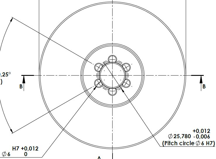
So, a 6 holes pattern of 6mm H7 is positioned on a pitch circle of 25.78 which has asymetrical tolerance.

So, I want to convert this asymetrical tolerance of (+0.012, -0.006) mm to a position tolerance. The pitch circle is now "basic".
Hole_pattern_V02_f59log.jpg


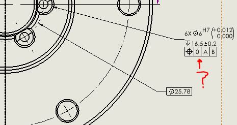
Is there a proper way to convert?
 
Replies continue below

Recommended for you

You have two tolerances. An angular tolerance that you haven't included and a radial tolerance that is part of the pitch diameter tolerance. What you did not have originally is an indication of what the pitch diameter was located from.

You can create bidirectional position tolerances, one radial and one tangential and figure the tangential tolerance using trigonometry from the original angular tolerance and the radius, to more adequately represent the situation.

Since the original fit was unlikely to be diametral a diametral position tolerance likely won't be appropriate.
 
Joel_Lapointe,

If you change your pitch circle to Ø25.783, you can apply a symmetric tolerance, and convert to positional tolerances.

--
JHG
 
Looking at the conversion image - you have clearly shown there is zero location tolerance at all.

Pretty good if you can get the machinist to do that.
 
Status
Not open for further replies.
Back
Top