Eng-Tips is the largest engineering community on the Internet

Intelligent Work Forums for Engineering Professionals

Baltimore Bridge collapse after ship collision 125

Replies continue below

Recommended for you

In the past, engines routinely had engine driven pumps. As the horsepower of the engines increased I think the transition was made to all electric pumps. My school's ship had engine driven pumps with electric backup but the engine drive pumps were so unreliable they were removed and additional electric pumps were added. The trouble is making 100+ horsepower pumps for lube oil or cooling water that can work with bi-directional shaft rotation for direct reversing engines.

Also consider that modern ships have a central fresh water cooling loop that is separate from the engine but necessary for the engine. These pumps would not be included in the engine skid as they will vary based on the requirements of the rest of the plant.

As for the size of the emergency diesel, the ship already has 4 diesel engines that are each capable of running the plant. Adding a 5th engine is not going to prevent this issue. The EDG is primarily for starting the ship from a cold iron state.

I did a stint on a 1975 built steamer. The EDG had enough power to run one boiler at minimum power and a service generator. It took about 3 hours to switch from EDG power to service power assuming the boilers were already hot.
 
Summary seems to be:

They only use ONE HV to LV transformer (out of two available) from the HV bus to power the LV bus for some unstated reason. I really can't understand why everything would hang off one set of breakers and TX when you could use two?? TXs don't exactly wear out do they? Any sparkies out there able to comment?

Anyone one of the TXs (no 2 set) had been in use for several months, then whilst in dock the single generator active at the time tripped because someone blocked the exhaust and stalled the engine... so they decided at the same time to switch TX and associated breakers when they brought the electrical system back to life. Even then they had a second electrical failure because they had fuel pressure issues on the next generator in line.

When under way and heading towards the bridge this no 1 set of TX and associated breakers unexpectedly failed / opened and as the engine requires support services powered by the LV bus, the main engine stopped. Just goes to show how non single failure resilient a ship this size is....

Then they couldn't get the electrical system back for long enough to re start the main engine.

Not sure what the plume of smoke was we saw, but could? have been the emergency generator (or generator no 2) clearing its lungs as it fired up and promptly went into full load as it may not have been used very often.

So the whys, how often and whether there was any warning of the electrical failure of the breakers is going to be the key issue here, plus lack of redundancy or back up for the main engine to be able to keep going in the event of one breaker opening when it shouldn't.

Remember - More details = better answers
Also: If you get a response it's polite to respond to it.
 
LittleInch said:
They only use ONE HV to LV transformer (out of two available) from the HV bus to power the LV bus for some unstated reason. I really can't understand why everything would hang off one set of breakers and TX when you could use two?? TXs don't exactly wear out do they? Any sparkies out there able to comment?

Circuit breakers are sized to protect the wiring and equipment they supply as well as the source. Connecting both transformers at the same time would cut the protection factor in two and defeat their ability to protect those circuits and equipment.

While transformers don't "wear out", they do degrade over time as the heat degrades the insulation and oil absorbs moisture. Breakers of this size on a ship will certainly require regular testing and maintenance. Having two sets on a ship would allow routine testing and maintenance to be performed on one set while the other set continues to be used to operate the ship.


[sub]
[/sub]​
 
diagramcopy_t7sw8c.png


Marked in red above, are the area(s) in loop during circuit breaker trips (LR1/HR1/DGR4/DGR3), but that are not in loop when Switched to DGR2 feeding HR2 thru common HVR buss to LVR.

Edit: 'Simple Simon' one-line electrical diagram for Dali was from NTSB report, linked earlier in thread..... I only added red marks.
 
Nukeman,

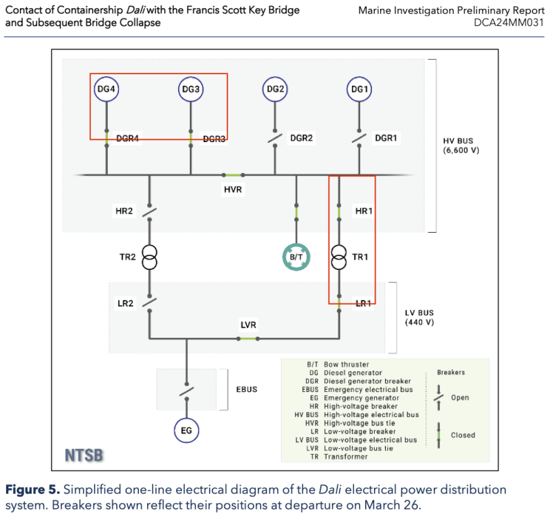
I kind of get that, but in this case all TR1 and TR2 is supplying is the main 440V bus, which is some huge great thick piece of copper rated at thousands of amps.

Everything off the bus then has the loads on it via their own circuit breaker.

Switchboards I've seen in plants look exactly like this, but I can't recall any that only operate with a single breaker closed onto the lower voltage bus for this exact reason - single point of failure. Or it operates in two halves with the bus tie normally open which is only closed when you want to do something to one of the TXs.

The breakers allow for each TX to be taken off line if they need to but not on a one off, one on switchover basis before.

The diagram for the emergency bus looks wrong as well. i'm used to the EB being powered from the main bus in normal operation, but then on loss of power, that breaker opens and the EG breaker closes once it's powered up. So there should be two breakers there, one from the normal bus normally closed and one from the generator normally open but interlocked with the incomer. Otherwise the EG endsup powering the whole 44V board...

Remember - More details = better answers
Also: If you get a response it's polite to respond to it.
 
DIk,

A bit simplistic and has errors in it. He thinks the EG is supplying the whole 440V bus! It only supplies whatever is on the emergency bus.

Remember - More details = better answers
Also: If you get a response it's polite to respond to it.
 
Using differential protection, having transformers in parallel has no adverse impact on protection performance. Having the load split between two transformers means half the total load loss and it also means that each transformer only absorbs 25% as much load loss heat as it would if carrying the whole load. Having both in parallel also means that if one trips the other is already there to continue to serve the load.

When one this sentence into the German to translate wanted, would one the fact exploit, that the word order and the punctuation already with the German conventions agree.

-- Douglas Hofstadter, Jan 1982
 
Thanks for the corrections... electrical is not my forte... I understood the NTSB provided the circuit diagram.

-----*****-----
So strange to see the singularity approaching while the entire planet is rapidly turning into a hellscape. -John Coates

-Dik
 
Seems like all roads lead to some sort of fault at TR1 or it's breakers. When they restored TR1's breakers, the second fault tripped the DG breakers instead (was the fault so large that TR1's breakers didn't even get the chance to trip the 2nd time?)

The fact that TR1 was not in use until recently (due to switching between them in port during the engine shutdown), further says maybe a problem was lurking on TR1 that surfaced once put under load.

With a fault large enough to trip both DG breakers on the HV bus the 2nd time, I'd expect some pretty obvious damage to whatever triggered the trip. Will be very interesting to see what condition TR1 is in currently...

The other obvious question is that when TR1's breakers opened, why didn't TR2 get switched in? (was it locked-out manually by the crew?) If there was a TR1 fault, it sounds like the automation failed to identify where the REAL fault was and determine that TR2 could be redundantly switched in...

Like most accidents, this sounds like a combination of issues (some of which may be design flaws?) that worked together to cause the disaster.
 
Even more reason why not having both TRs connected is such a strange decision when in port. Maybe they should have had the EG running as well...

When loss of 440V shuts off your only propulsion for several minutes you should be doing everything to make sure it doesn't happen.


Remember - More details = better answers
Also: If you get a response it's polite to respond to it.
 
In playing with the various simulators I posted about a while up on the thread, even before the accident, I had noticed that on the ships that had redundant transformers just like this one, there was an interlock on all of them so that both transformers could not be connected at the same time (ie, in parallel). I was kind of surprised by this, too. But it seems to be common practice if the multiple simulators I saw having it are any indication.

As was discussed before, the diagrams presented by the NTSB are obviously simplified. In the simulators, most of the designs actually had several transformers arranged like this (in pairs) between various other busses--and ALL have interlocks.

Example (from a 10020 TEU ship simulation):
93 and 104 are examples--see the interlocks?

bustie_ecflaz.png
 
Roga50 said:
With a fault large enough to trip both DG breakers on the HV bus the 2nd time, I'd expect some pretty obvious damage to whatever triggered the trip. Will be very interesting to see what condition TR1 is in currently...

I've not yet read the finer detail of the report, just following the commentary on it for now. Does it specify that they tripped on overload? The more sophisticated breakers can trip for a variety of reasons, such as under/overvoltage, earth fault, arc fault, off-frequency, remote trip from a management system, etc.
 
Not yet said. Just says " unexpectedly opened/tripped".

Remember - More details = better answers
Also: If you get a response it's polite to respond to it.
 
I believe the reason interlock the transformers has to do with synchronization. The transformers are not rated to the loads associated with synchronization. If the HV bus tie breaker were to open than any anomalies such as motorization would feed from the LV bus through the transformer back to the generators on the other HV bus. Assuming the transformer MVA is much lower than the generator MVA, this could be a problem for the transformer.
 
Hey Tug, where did you find the transformer rating?
An educated guess is no better than an uneducated guess at this point.

All synchronization would need to happen before closing the breakers to the HV bus (DGR1, DGR2, DGR3, DGR4) and generators that were out of service would not be connected to the HV bus.

We could speculate that each transformer is only rated for two generators so they only need both transformers when three or four generators are running. Only two are needed for normal operations but I can see refrigeration being a greater load in summer months for example.

The EG may be locked out from the low voltage bus unless LV1 and LV2 are both open. We know there are other loads that it feeds that are not shown in this simplified one line drawing, but without seeing the big picture with all the fine print notes and a sequence of operations, how could we know how any of it works?

Until we get more details on how this ship operates, we are just spinning our wheels.

[sub]
[/sub]​
 
There hasn't been much coverage of this situation...

Crew trapped on Baltimore ship, seven weeks after bridge collapse


An excerpt from the above item:

The simultaneous blasts sent pieces of Baltimore's once iconic Francis Scott Key Bridge into the dark waters of Maryland's Patapsco River, seven weeks after its collapse left six people on the bridge dead and the Dali marooned.

Authorities - and the crew - hope that the demolition will mark the beginning of the end of a long process that has left the 21 men on board trapped and cut off from the world, thousands of miles from their homes.

But for now, it remains unclear when they will be able to return home.

The Dali - a 948ft (289m) container ship - was at the start of a 27-day journey from Baltimore to Sri Lanka when it struck the Francis Scott Key Bridge, sending thousands of tonnes of steel and cement into the Patapsco. It left the ship stranded under a massive expanse of shredded metal.

A preliminary NTSB report found that two electrical blackouts disabled equipment ahead of the incident, and noted that the ship lost power twice in the 10 hours leading up to the crash.

The crew, made up of 20 Indians and a Sri Lankan national, has been unable to disembark because of visa restrictions, a lack of required shore passes and parallel ongoing investigations by the National Transportation Safety Board (NTSB) and FBI.

On Monday, the crew remained on board even as authorities used small explosive charges to deliberately "cut" an expanse of the bridge lying on the ship's bow.

Ahead of the controlled demolition, US Coast Guard Admiral Shannon Gilreath said that the crew would remain below deck with a fire crew at the ready.

"They're part of the ship. They are necessary to keep the ship staffed and operational," Adm Gilreath said. "They're the best responders on board the ship themselves."


John R. Baker, P.E. (ret)
Irvine, CA
Siemens PLM:

The secret of life is not finding someone to live with
It's finding someone you can't live without
 
It is still a ship at sea and must be manned.
That is most of the reason why the crew is there.
I just hope that we are doing a better job of supporting them than in some cases that I have heard of.

= = = = = = = = = = = = = = = = = = = =
P.E. Metallurgy, consulting work welcomed
 
Since authorities have seized their cell phones, I'm sure that some of them are feeling like they're 'trapped'. Granted, they've probably been kept busy, but being cut-off from their families has got to be a hardship for many of them. After all, if this accident had not occurred, most of them would have probably made it home by now, or at least to a port-of-call where they would have been allowed to leave the ship and perhaps meet with friends and family.

John R. Baker, P.E. (ret)
Irvine, CA
Siemens PLM:

The secret of life is not finding someone to live with
It's finding someone you can't live without
 
Back
Top