Continue to Site

Eng-Tips is the largest engineering community on the Internet

Intelligent Work Forums for Engineering Professionals

  • Congratulations waross on being selected by the Eng-Tips community for having the most helpful posts in the forums last week. Way to Go!

Beam connection stability 7

Status
Not open for further replies.

Vrpps EIT

Structural
Aug 21, 2018
58
CA
Hi All,

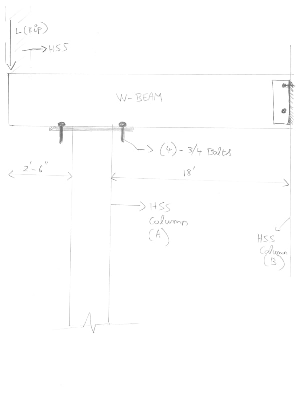
Attached the situation in the pic, under this loading, when the overhang portion has a column on top of it and has a point load. This creates a moment at the beam and column-A connection. which in turn will create an uplift load. So, this uplift will be resisted by the beam & column-B connection at end of the beam which is fixed there or the four bolts that are connected at beam column-A connection? Or in simple terms what tensile force should the 4 bolts at column support A near the overhang to be checked for is it the reaction force that support will carry?
I can see it as a tower crane with balancing counter jib but I am missing something here.

Thank you for your time!
 
 https://files.engineering.com/getfile.aspx?folder=2e3d4853-5d88-4ea1-a52b-861a35338f7a&file=Scan001_(5).jpg
Replies continue below

Recommended for you

Yes retired13, that is shown on the sketch in the original post.

BA
 
BAretired said:
There has been no mention of "simple snug tight bolted cleat connections". The OP's sketch indicates an HSS column at the end of the cantilever with no description of its connection to the beam.
Well from the drawing I can see something something that looks awfully like a two bolt cleat connection. In the absence of further information I'll go by that.

BAretired said:
There is no indication of the load on that upper column, so it is possible that a cap plate would be needed, not to mention a stiffener under one or both walls of the HSS.
You are going to have to elaborate here.

BAretired said:
How could you be proven wrong and how could anyone have research on something as ethereal as this?
Ethereal? This is REAL engineering not ethereal. And yes people have done research on this, a quick google shows this. I'm sure there are hundreds.
 
human909 said:
Well from the drawing I can see something something that looks awfully like a two bolt cleat connection. In the absence of further information I'll go by that.

The only bolts I see are in the beam to Column A connection where there are 4 - 3/4" bolts. I'm talking about the connection between the upper column bearing down on the end of the cantilever. If you can see a two bolt cleat connection there, then you either have better vision than I or better imagination.

CantConn_jy2twe.jpg


BAretired said:
There is no indication of the load on that upper column, so it is possible that a [highlight #EF2929]cap[/highlight] plate would be needed, not to mention a stiffener under one or both walls of the HSS.
human909 said:
You are going to have to elaborate here.
Sorry, cap plate should read base plate.
human909 said:
Ethereal? This is REAL engineering not ethereal. And yes people have done research on this, a quick google shows this. I'm sure there are hundreds.
It is not just a matter of connecting column to beam for a particular reaction. It is also a matter of bracing the beam to prevent overturning. It is indeterminate in the sense that we do not know whether any bracing exists other than the column connections. Nor do we know the magnitude of loads on the span or cantilever.

BA
 
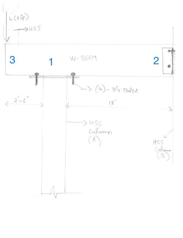
Everyone is referring to different connections and arguing as a result (“cleat connection?!? That’s not a clear connection!!”). We should number them if discussion is to continue.
 
Good idea, Tomfh. I suggest we number them connection 1, 2 and 3 for connections to Column A, B and C respectively. Column C is the HSS above the beam, which bears on the end of the cantilever.

BA
 
Unless the beam is braced to resist torsion by elements not shown on the sketch, Connection 1 should be designed to prevent overturning. This could include stiffeners aligning with the HSS walls.

Connection 2 is deemed a pin with regard to beam bending but must prevent torsional rotation.

Connection 3 must be adequate to transfer the axial load from Column C to the beam. Depending on the magnitude of axial load, a stiffener may be required in the beam.

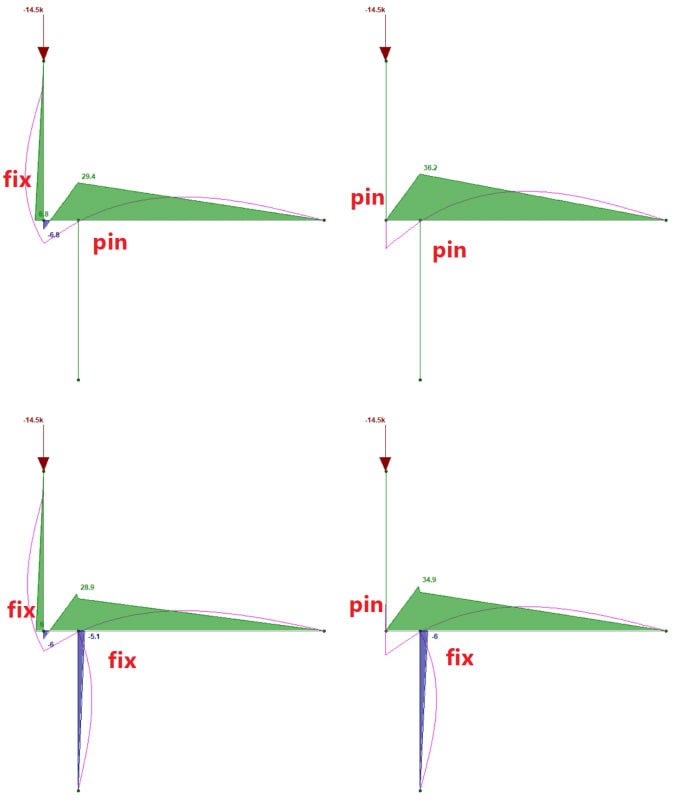
The stiffness of Columns A and C must be considered when analyzing the distribution of moments in the structure.

BA
 
I envision this is an industry platform, with handrail on top of channel connected to the tip of the cantilever. In turn, the channel braces the beam in conjunction with floor beams in the transverse direction. The lateral load from the handrail will produce a moment on the tip of the beam, and a vertical reaction on the HSS column below. These loads should be add to the analysis results done previously. Note the direction of this additional moment, if reversed, may help to relieve the forces in the beam and column below, I'll check the effects with cautious.

b_bzyevr.png
 
Wow! First, a two bolt cleat connection; now a channel, floor beams and a handrail. How did I miss all of this stuff? My eyesight must be worse than I thought.

BA
 
Engineering imagination to make matter simple:) It can be another framing system on top, and there could have, or no slab after all. We can only speak for question on hand with given information, that is a cantilever framing system with a load on the free end. The story has ended long time ago.
 
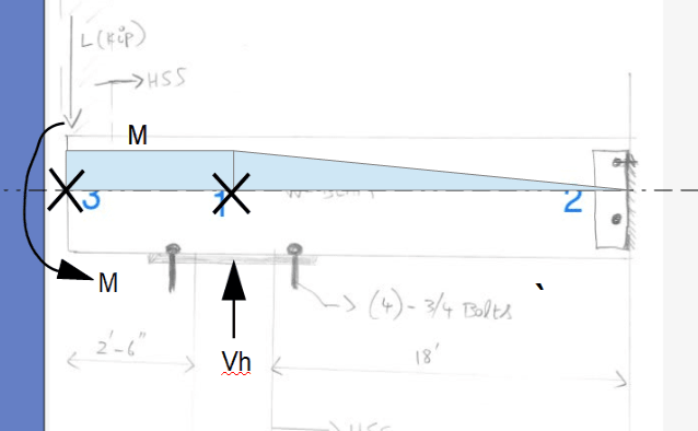
Yea I don't know about a handrail and a channel. Seems to me like OP has a column above and below in a transfer condition. Plus that moment diagram would look different for a point load on a cantilever with a couple.

BA is right, all member fixities matter of course. It's a matter of how you decide to approach the problem.

engtips_col_beam_connex_q11nhm.jpg
 
Status
Not open for further replies.

Part and Inventory Search

Sponsor

Top