Continue to Site

Eng-Tips is the largest engineering community on the Internet

Intelligent Work Forums for Engineering Professionals

  • Congratulations waross on being selected by the Eng-Tips community for having the most helpful posts in the forums last week. Way to Go!

Beam connection stability 7

Status
Not open for further replies.

Vrpps EIT

Structural
Aug 21, 2018
58
Hi All,

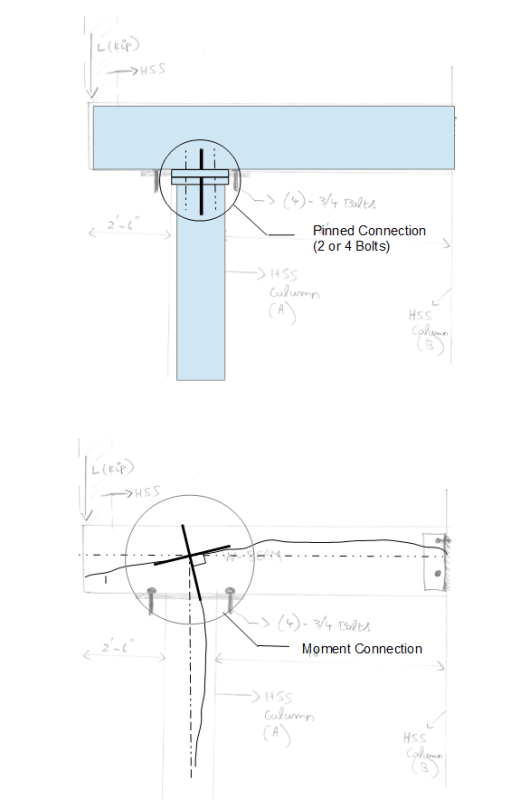
Attached the situation in the pic, under this loading, when the overhang portion has a column on top of it and has a point load. This creates a moment at the beam and column-A connection. which in turn will create an uplift load. So, this uplift will be resisted by the beam & column-B connection at end of the beam which is fixed there or the four bolts that are connected at beam column-A connection? Or in simple terms what tensile force should the 4 bolts at column support A near the overhang to be checked for is it the reaction force that support will carry?
I can see it as a tower crane with balancing counter jib but I am missing something here.

Thank you for your time!
 
 https://files.engineering.com/getfile.aspx?folder=2e3d4853-5d88-4ea1-a52b-861a35338f7a&file=Scan001_(5).jpg
Replies continue below

Recommended for you

How is doing moment distribution by hand any simpler than plugging it into a structural analysis program?
 
Tomfh said:
How is doing moment distribution by hand any simpler than plugging it into a structural analysis program?

Agreed. My solution to this problem that I've dealt with in the past is to ensure that the system works for BOTH a fully rigid and a fully flexible connection.

Most connections and in particular bearing connections like this are going to transfer some moment unless you are go to alot of effort to detail a pin.

retired13 said:
If you are taking this approach (moment distribution in rigid joint), you have to make sure the beam and the column are rigidly connected, otherwise, the moment distribution will not happen, or result in partial distribution (that nobody knows how much.
Which isn't a problem if the two pinned and moment come out fine. If you are concerned that "nobody knows how much" then you need to consider this is true of the majority of the connections out there. All have a degree of stiffness.
 
Vrpps,

To make a pin support, just use 2 or 4 bolts, and place the bolts inside of the column foot print with minimum bolt spacing. The bolts shall be sized for uplift and horizontal shear, if any. The beam needs to be designed for the full moment caused by the cantilever, regardless of how the connection is made.
 
Why would we opt for a more expensive, rigid connection though? And a bigger column. The whole discussion pretty much boils down to: "Assuming this connection were to induce some amount of moment into the column, what is the mechanism and what is the expected magnitude?"

I'd check it for either: entire reaction at column edge if the beam is very rigid compared to the column, or entire reaction at the tip of the cap plate (under the beam web) for a much more rigid cap plate and column. Or rather, "what sort of rotation do I expect to see at this end of the beam". That would apply to a simply supported beam as well.

If you wanted to, you could think of a sort of triangular stress distribution along the length of the beam web. Ultimately there is some resultant point load roaming around on the cap plate somewhere between the center of the column and the edge of the cap plate. That is your eccentricity. That would take a long time.

Depending on the situation (length of cap plate, judgement, etc) you might end up with similar, slightly conservative, yet much quicker results compared to a moment distribution: 17k*6in=8.5k-ft (assuming a thick, 12in long cap) vs. 5.81k-ft (moments from discussion above).

For the sake of argument, say the column is infinitely stiff and we're doing this moment distribution excercise. Column takes all of the moment from the propped cantilever. Would you really design the connection to take the full moment? You wouldn't design the beam for zero moment between the column and backspan support would you?
 
tomfh said:
How is doing moment distribution by hand any simpler than plugging it into a structural analysis program

Was that meant to be a question for me? I"m afraid that I've lost track of who's talking to whom.
 
retired13 said:
To make a pin support, just use 2 or 4 bolts, and place the bolts inside of the column foot print with minimum bolt spacing. The bolts shall be sized for uplift and horizontal shear, if any. The beam needs to be designed for the full moment caused by the cantilever, regardless of how the connection is made.
Except it isn't that simple. The connection drawn and described can and does transfer moment. Whether this matters depends on the column and beam.
 
kootk said:
Was that meant to be a question for me? I"m afraid that I've lost track of who's talking to whom.

Not just you. There's a number of you discussing moment redistribution as an option.

I was wondering why you'd bother doing that instead of modelling it with a 2D frame program, which will do it faster and more accurately.

dold said:
For the sake of argument, say the column is infinitely stiff and we're doing this moment distribution excercise. Column takes all of the moment from the propped cantilever. Would you really design the connection to take the full moment? You wouldn't design the beam for zero moment between the column and backspan support would you?

I'd design the beam and connection assuming it's a pin and the column assuming it's a rigid connection.
 
tomfh said:
I was wondering why you'd bother doing that instead of modelling it with a 2D frame program, which will do it faster and more accurately.

Got it, thanks. On my end:

1) I wouldn't have done anything for this condition other than to call it a pin and move on so that's really where the efficiency would lie.

2) I only did the moment distribution so that a) we'd have have a meaningful number to discuss and b) to show OP an expedient way to estimate the parameter he sought.

3) My hand calc was 100% accurate and took about 30 seconds to execute. Little time wasted there in not firing up FEM. In less ridiculously simple scenarios I would pull the numbers from an FEM software run.

tomfh said:
I'd design the beam and connection assuming it's a pin and the column assuming it's a rigid connection.

That strikes me as an efficient and reasonable approach. It's really the connection where you'd potentially hemorhage time and fabrication cost.
 
So far, no one has mentioned the moment taken by the HSS at the end of the cantilever (which may serve to reduce the applied moment. And, looking back at the initial diagram, depending on the magnitude of the load, there should probably be a stiffener at the right hand side of the column above and the left hand side of the column below.

Without some stiffening, the web of the beam tends to be unstable. Beams framing into the W10 could provide stability.

BA
 
BAretired- I agree with adding a stiffener but in general when the shear capacity of a beam or the compression capacity of the web in a beam is 2 to 3 times greater than the actual point load from the column above or below, why is it always the stiffeners are added in the beam when a column is located above or below it? is it a general practice or?
 
When a beam is continuous over a column as your sketch shows, there is the potential for a severe stability problem. The compression flange of the beam tends to buckle sideways and simultaneously, the beam column junction tends to buckle sideways because the column is in compression. Lateral restraint must be provided, either by extending the bottom chord of a joist to the column, adding a stiffener or relying on the stiffness of the web. The latter is difficult to assess and a more positive restraint is to be preferred.

BA
 
Agree with BA. Stability due to side sway is always a concern for beam cantilevered over a column.
 
c_lqlcyb.png
 
Tomfh said:
I'd design the beam and connection assuming it's a pin and the column assuming it's a rigid connection.

kootk said:
That strikes me as an efficient and reasonable approach. It's really the connection where you'd potentially hemorhage time and fabrication cost.
Far from it. You don't need to design the connection tho be fully rigid.


Retired13. While your connection is less rigid than the initial one there is still scope for moment transfer. Rigid plates bearing on each other with a compressive load can and will transfer moment if they are relatively wide.

(If you were to have a just two bolts AND central shim plate separating the two plates then you would start to see pin type behavior.)
 
human909,

As we been told over and over, no connection is perfectly rigid, or pinned, we can only try to minimize the undesirable factors. Note that no matter what type of connection is made for this situation, the beam has to be able to resist the full moment from the cantilever; for the column, if it is pinned, it shall be designed/checked for the axial load with code specified minimum eccentricity to produce a moment. So, the design remains correct and conservative.
 
Any to demonstrate for Retired13. Here is your example with a single bolt.

1_h7flmv.png


I ran it a few times with different connection details. In this scenario it behaves more like a rigid connection than a pinned connection.

(In case you are wondering. Yes I am modelling the bolt sensible tightning torque. And yes there was some sepparation and differential rotation in the connection. But overall it wasn't huge because the connection was still relatively 'stiff')

NOTE: Some people like pictures and computer analysis, some prefer their pencil. Both approaches work if they are a reasonable model to reality. The reality of this I have seen. The structural engineers response was: "I designed it as a pinned connection".

Unfortunately it didn't behave like a pinned connection!!
 
retired13 said:
for the column, if it is pinned, it shall be designed/checked for the axial load with code specified minimum eccentricity to produce a moment. So, the design remains correct and conservative.
I disagree.

In some circumstances the design is not conservative as there IS moment transfer with this type of 'pinned' connection. Ignore it at your peril. The amount depends on the connection and the beam curvature but it can certainly be non insignificant.
 
Human said:
Far from it. You don't need to design the connection tho be fully rigid.

That’s what I said. Design the beam and connection
assuming it’s pinned. I.e. don’t bother designing the connection as fully rigid.

But for the column assume it’s rigid because in reality the column will attract moment.
 
Sorry Tomfh. I quoted you but never replied. Yes I agree with you entirely. :)

The approach you outline is conservative.
 
human909,

The bent does not maintain 90°. Did you try the parameters and load used by OP? When you have a 35 k-ft moment at the joint, report beck the share of the beam and the column. If does not match previously analyzed above using rigid joint distribution, then either the classic method is wrong, or your model is incorrect. Also, what type of element representing the bolts, its rigidity? You shall enlarge the joint to shown the connection and distortion of beam-column interface to make sense.

[ADD] All column deforms under load, for pin-pin, it bend into a bow; for fix-pin, it shall show. a straight portion to maintain right angle with the deformed beam. For partial fixity, the moment in the column should be negligibly small, if any. The small moment induced reflects the conventional wisdom that there is no perfect pin, nor fixed support, especially with the limit capability on modeling for the former.
 
Status
Not open for further replies.

Part and Inventory Search

Sponsor