Continue to Site

Eng-Tips is the largest engineering community on the Internet

Intelligent Work Forums for Engineering Professionals

  • Congratulations KootK on being selected by the Eng-Tips community for having the most helpful posts in the forums last week. Way to Go!

Boeing 737 Max8 Aircraft Crashes and Investigations [Part 5] 19

Status
Not open for further replies.

Sparweb

Aerospace
May 21, 2003
5,109
This is the continuation from:

thread815-445840
thread815-450258
thread815-452000
thread815-454283

This topic is broken into multiple threads due to the length to be scrolled, and images to load, creating long load times for some users and devices. If you are NEW to this discussion, please read the above threads prior to posting, to avoid rehashing old discussions.

Thank you everyone for your interest! I have learned a lot from the discussion, too.

Some key references:
Ethiopian CAA preliminary report

Indonesian National Transportation Safety Committee preliminary report

A Boeing 737 Technical Site

Washington Post: When Will Boeing 737 Max Fly Again and More Questions

No one believes the theory except the one who developed it. Everyone believes the experiment except the one who ran it.
STF
 
Replies continue below

Recommended for you

Ford pioneered the self energizing brakes.
Dodge and GM were years behind.


Bill
--------------------
"Why not the best?"
Jimmy Carter
 
I was only trying to think of an example that people could relate too about having a control which gave none linear responce to linear input that was universal across all flavours of engineering.

The old plant had some nonlinear responces to hydralic inputs mainly due to variations in circular orifice as you opened up a control. But I discounted that example as I presume it will only be a select few who have had to sweat htough that learning curve.


I might add that all the digger operators that I taught to fly the manual manipulation skills were "taught" in seconds. NAviagtion though was a bit more of a challange for them.


I might add I hired a small tracked digger last month to shift some crap on the farm. I was quiet surprised how quickly it all came back, like riding a bike. Must have been 20 odd years since I had to operate one. Changed quiet a bit since then all the controls are linear response and rate of movement is linear. No more slowly slowly movement with deflection of the stick then a ball hair more stick and the arm triples in movement rate.


Most youngsters these days will have never had to get to grips with nonlinear controls. And if Boeing get their way they are meant to be able to deal with them in 3 seconds response time after reading about them on a Ipad with loads of alarms going off. And if they screw it up the electric trim is gone thanks to the new dual FCC killing the trim system if it spots a mismatch and the speed goes up by 50 knots they haven't got the strength to turn the wheel with out doing a rollercoaster manoeuvre.
 
waross said:
Asking, not telling, but when the stick feel "goes light" are you at, or dangerously close to a point where the AoA will continue to increase into a full stall unless the stick is pushed ahead?

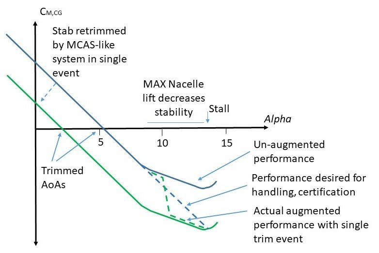
Speculating, not knowing, I will offer this opinion, based on a curve that circulated on the internet several months ago. It looks plausible, but the source is not confirmed to be valid, therefore this is NOT factual. Just some ideas, related to this question:

737max_Cm_Curve_Speculative_r8jnxr.jpg


This curve represents a pitching moment curve, which is the moment that is counteracted by the tail. The moment must be counteracted by an opposing force at the tail for the aircraft to maintain any constant angle of attack. Trimming the tail changes the angle of the tailplane, which forces the aircraft to assume a different "trimmed" angle of attack. Usually this is done in very slight increments, not the exaggerated change in the graph above.

The graph shows several different pitching moment curves, intended to illustrate someone's attempt to explain how MCAS works.
1) the blue dashed line represents the preferred pitching curve which is linear and consistent through most of the flight envelope,
2) The blue solid line represents the pitching curve that may have resulted from the 737 max engine configuration change,
3) The green solid line represents the 737 max pitching curve after it shifts with a change in tailplane trim pitch,
4) The green dashed line represents the transition from one pitching curve to another as the MCAS operates to add some tailplane pitch.

So the graph seems to have some exaggerations, but it's useful to show how the system might be functioning. A few adjustments to the rate of MCAS pitch changes would allow the green dashed line to follow the blue dashed line more closely. As it is, I believe the graph is just printed the way it is for illustration and clarity, not to correspond to any actual data points. Another possible consequence of this kind of pitching behaviour could be that the control forces get lighter at higher angles of attack; another thing that corresponds to the reports we are hearing.

I hope you find that helpful, and answers your question.

 
Thank you Steven.


Bill
--------------------
"Why not the best?"
Jimmy Carter
 
Just asking a quick question - From what I understand the two FCCs on the 737 operates on a working / standby or side to side configuration?
Would switching the FCC from the side going nuts (in both cases the captains side) have made any difference?

Either way I can't see how these apparently proposed AOA or FCC disagree functions is going to work if the answer is turn them off / disregard the signals. Also by how much can they disagree and still be OK? From the graph above it looks like only a few degrees. How accurate are these things?

Fundamentally the 737 max has flying characteristics which means MCAS is required to meet the certification rules of constantly increasing stick force vs AOA. No MCAS or FCC then it just opens up another hole in the swiss cheese.

The other aspect is the size of the stabiliser vs the force from the manual wheel means it can't realistically be used as the back up once the speed goes up a bit. So this would need an additional actuator or a whole new set of standalone "manual" wiring to the jack screw.

Hence two massive issues to try and resolve without either making large mods to the several hundred aircraft already out there and / or needing the pilots to all train and re-certify for this variant of the 737.

Kind of tells the reason why it hasn't happened yet I feel.

Remember - More details = better answers
Also: If you get a response it's polite to respond to it.
 
I suspect that the best technical fix is to use 4 AOA devices, but if Boeing agrees to this , then it implies the use of one active AOA was "negligent", which is the legal N word that no company wishes to have to respond to in court.It may also occur that the investigation of Boeing actions that effectively muted engineers' cautions and prohibitions re: use of a single AOP constituted a conscious effort to accelerate the deployment of the aircraft then the N word could again be used in court. If a judge deems the N word is valid, then there is no financial limit to the damage awards, and it would spell the end of Boeing.

"...when logic, and proportion, have fallen, sloppy dead..." Grace Slick
 
On the one hand there are a lot of jobs and a lot of loyalty towards Boeing.
On the other hand, there may be a limit to the physical size of engines relative to the physical size of an aircraft.
That limit may have been passed with the Max.
Looking forward to future designs, not as a fix to the Max:
Larger fans yield greater efficiency.
Big engines are not going away.
But when we look at the cutaway of a leap engine without the bypass ducting, it is quite narrow waisted.
Is it feasible that future engines will be mounted much closer to the center of lift with part of the bypass ducting passing over or through the wing?
Dave said:
and it would spell the end of Boeing.
Does anyone remember Konica and their one bad design choice?

Bill
--------------------
"Why not the best?"
Jimmy Carter
 
Bill said:
Does anyone remember Konica and their one bad design choice?

I remember old Koni stuff I used to have a Koni C35 AF, the first production autofocus camera. When you pressed the release, the lens would move from the infinity position to the near limit. When the rangefinder images matched, it would stop the lens and release the shutter. The guy who shot some of my wedding pics used a Koni Omega 6x7

At the george eastman house you can see the a prototype, the first working digital camera, made by Kodak. They were famous for something else though, but it escapes me...., printers maybe?

 
Regarding powerplant size, there was a step change when turbojets overtook piston engines, not to mention turboprops, as the powerplant of choice for large airliners. If you take axial cross section for powerplant size, then this was an enormous reduction, and since then size as a function of thrust has been steadily increasing. Yet we're far from being all the way back to pure propellers as far as specific size goes (nor even absolute size), and I doubt we ever will get there. I don't rule out open props again on the largest airliners in the long run, but I suspect in that case that thrust as a function of disk area will be much higher than the previous norm.

"Schiefgehen wird, was schiefgehen kann" - das Murphygesetz
 
A report is due out on the process. f you do the private window opening and hit stop in the browser you can read it without having a subscription.


" How accurate are these things?"


Normal range is -20 to 20 deg and 1 decimal place output to the FDR. Normal operating range is 3 deg to 16 deg.

If they had worked out it was FCC problme they can switch them, you can switch ADC's and AHARS as well. BUt you can't switch the sensors. The big problem is working out which one is giving duff info. The primary airdata you use the independant standby horizon instrument as the reference.

"Is it feasible that future engines will be mounted much closer to the center of lift with part of the bypass ducting passing over or through the wing?"

Already been done see the design of the comet. Having the engines in pods where if they fail they don't take out the fuel tanks is one factor, second is hot gas inside the wing is not good. the third is for ease of maintence. They can swap a engine on a 747 in under 12 hours and 3 tech's and a crane and the 747 has a 5 th pylon so they can even take a spare with them.


The biggest limitation with props is the tips going super sonic.


Only other thing to note is that Indian has gone with EASA certification. So thats a quarter of the orders now being officaially certified seperately.
 
I just had to go look up the 5th pylon thing. I thought you were joking!
Anyway thanks for responding. On the FCC is it actually a side by side thing (i.e. one handles instruments, inputs etc from one side and the other one the other) or is it more complex than that?
Would the other FCC still have been using the incorrect data from the AoA indicator?
Why was it only the captains side which had the stick shaker etc going off?

I assume from previous comments that the FBW planes use a 2003 voting system to decide a faulty system. A 1002 system therefore doesn't seem to cut it in terms of knowing which input / machine is at fault. Hence the pilot(s) become the arbiter.


Remember - More details = better answers
Also: If you get a response it's polite to respond to it.
 
The effect of engine size on aircraft trim.
The larger size engines have been mounted further forward and lower in relation to the Center of gravity.
The larger engines cause more uplift as the angle of attack increases.
When the engines are mounted far forward of the center of gravity the uplift has a greater mechanical advantage and so a greater effect on the trim at higher angles of attack.
The complete solution is to move the engines back so that the center of the uplift force is under the center of gravity.
Now we have lift rather than trim upset.
The other effect is the trim upset caused by thrust below the center of gravity.
The lower the engine is mounted below the CoG the more mechanical advantage the thrust has in causing trim upset.
The complete solution is to raise the engine so that the center of thrust is in line with the CoG.

The perfect solution to trim issues with large diameter engines is for the engine center of thrust and the engine center of uplift to coincide with the CoG.

Unfortunately the world is not perfect and I doubt that the engines will be so mounted in the near future.
However the bare engine may in the future be mounted close below the wing with the fan close to the leading edge of the wing.
That will put the hot gases below the wing and make the engine relatively easy to dismount.
The major bulk of the engine is ducting for relatively cool bypass air.
The ducting is relatively forgiving. It may be easily split to allow the engine to be dropped out.
The inside does not have to be the same shape as the outside, the outside may be in the form of an airfoil to generate added lift at all times, not just at high angles of attack, and the lift would not cause major trim upsets.

I consider many of the objections as engineering challenges to be overcome rather than reasons why a concept will not work.

To date there have been over 300 lives and billions of dollars as a testament that the present trend of mounting physically larger engines further ahead and lower may not be the best idea.

Bill
--------------------
"Why not the best?"
Jimmy Carter
 
In a previous thread there was a system diagram with the setup.

Each type is different. Fbw is a whole different setup.

There is fail safe, fail passive setups.

In theory it's relatively simple in a fail passive setup which the 737 is meant to be, but in practice there are more links than they tell the pilots about.

The sensors don't directly connect to them. They go to an air data computer. Which then outputs to various box's. The stall protection has two boxes one left and right which can trigger the stick shakers. When both shakers are on then it arms the hydraulic stick push system which is a piston which pushes the control column forward. These maybe separate boxes or combined with others system management boxes depending on the type.

A switch to running everything off one air data computer might also have helped. It all depends how it was wired.
 
And an interesting bit of info I found out yesterday.

The 737-200 300 and 500

All had 2 electro hydraulic trim motors driving the stab. One was used by the auto pilot and systems and the other was only used by the electric manual thumb switches.

The two cut out switches on the MAx are a legacy from those days you could independantly kill one or the other on the classics.

On the NG they replaced the two drive units with a single electrical screw jack. BUt kept the ability sort of kill either manual trim or system trim independantly.


And the max which is now electrical single screw jack and two switches in series so they didn't have to change the cockpit layout. Either switch will kill everything.

So in the classics you had two additional failure layers before you were into pilot brut force trying to manually trim the aircraft and you also had 1 layer of redundancy. Which complies with certififcation and gets you into a low level of failure mode easily into less than 1 in 1 million flight hours.


NG removed the redundancy layer but retained one failure layer.


MAX no redundancy and no failure layer = two fatal accidents with the trim system.
 
I assume with two motors there must have been some sort of interlock to stop the two trying to go in different directions at the same time. I guess in the MAX this was in the electrical switch and relay wiring diagrams posted some time ago.

But still makes the point that the manual system was able to be standalone and de-coupled from the FCC before and now it isn't.

I still think this will be a sticking point between Boeing and the regualtors or the European ones anyway.

Some re-wiring might be needed....

Remember - More details = better answers
Also: If you get a response it's polite to respond to it.
 
there isn't two motors on the max.

Its just one big electrical screw jack.

The classic had one motor for the automatics and a completely independent system and motor for the manual trim system. When you use the manual trim thumb switch it kicked the automatics out and took the other motor off line. Per say the manual system was never connected to the automatic system apart from a kill relay. But then again the classic didn't need to have any flight control augmantation to sort out dodgy aerodynamic effects.
 
just a couple of updates it seems the lionair report is out in November and they are doing the tidy up meetings.


Also the new boss of the FAA has had a pole of the max in the simulator with the new software. Whats telling for me is the fact that nothing has been said about none normal handling. And Ryanair are saying Feb/March.

 
Although this story was in March, it still resonates that the pilot was the fail safe, but no additional training was mandated. I know there is the " A properly trained pilot..." thread in this, but if you're going to sell your airplane worldwide then you need to sell something that still works when the level of training may not be at US / European levels. It does note that pilots, especially newer ones, now expect a level of automation that may not have been present in the MAX.

Still doesn't mention the fact that the manual back up system may not work due to the size of the stabilizer.

I'd not heard of this one before but shows that even 2003 voting doesn't always work if the 2 are frozen solid. Like a lot of incidents there were a LOT of other things not being undertaken correctly, but does show nothing is infallible.

Remember - More details = better answers
Also: If you get a response it's polite to respond to it.
 
Re the 5 pylon 747 there was a 4 engine B-17 WW2 bomber converted to use a 5th engine for testing purposes by P&W in late 40’s for turboprops. All 4 recips would be shut down with the turboprop maintaining flight power. I saw the airframe at the Bradley museum in Windsor Locks early 70’s sans the 5th engine but it since has been restored to original production config. Not a 5th pylon but still pretty cool. Here is a brief story about it.

 
Status
Not open for further replies.

Part and Inventory Search

Sponsor