Eng-Tips is the largest engineering community on the Internet

Intelligent Work Forums for Engineering Professionals

Boeing again 47

I'm trying to understand the rudder components and came across these OLD schematics and photos (YouTube video). I don't know how newer model components depart from the old systems so I'm offering these as a start point. Please speak up if I'm off track. The damage in this incident is related to the Standby PCU which is the upper set of components. It looks as though the system is fighting itself to produce the amount of damage seen in the photos of the frame and bracket (posted above).

Schematic_yxmgl6.png


Rudder_Pieces_wppee4.png
 
Aviation Investigation Preliminary Report said:
A new control rod was installed and during the rigging/adjustment of the main rudder PCU, maintenance identified additional structural damage to the rudder system in the area surrounding the standby rudder PCU.

This defies logic. After a significant control incident, a small issue was identified and repaired. As they were tiding up, a huge issue was discovered. Srsly? So is it possible this aircraft could have been returned to active duty with no one ever inspecting the standby unit? Is this how control issues run amok?
 
There is gross deformation of the failed support bracket. The photo does not provide adequate viewing angle to discern, but it appears that the standby HW has no clearance to this bracket. The kind of force needed to make this deformation would be a hydraulic one. It is as though there was a misaligned power mechanism or an adjustment out of spec such that min clearance was not maintained.
 
It looks like the rear fuselage is in place coming from Spirit: In any case this all appears to be within the vertical stabilizer and is essentially independent of the fuselage.

It is typical that hydraulic systems are force limited - there is a limit to the force they can generate, which is what makes them so durable in the hands of construction workers - push too hard and the pressure relief opens and the item moves. It is typical for the support structures strength to greatly exceed the forces the hydraulic system can produce.

The way to get the damage shown is by getting a cylinder to end of travel and then continue to push or pull on it with an external force beyond restricting the hydraulically operated travel.

---

Then tire manufacturers started adding carbon to the tire material to make it conductive enough to discharge static.

Carbon has been a key ingredient in tire manufacture for a long time; it is key to preventing UV damage and dates from the early 1900s. In the 1970s tire makers started using silica as a filler to reduce rolling resistance and increase wet grip. This made electrostatic buildup worse.

I never noticed getting shocked when the car seats are not made of certain materials; the shock in the winter from rubbing the seat of the pants and the back of the jacket against the seat covering material.

The static discharge straps may just be what sells rather than what does some good.
 
That looks like a significant overload fracture of the fitting, not a fatigue failure. Crazy and a bit disturbing; that should not happen. The plane is less than 2 years old.
 
3DDave (Aerospace) 10 Jul 24 19:55 said:
The way to get the damage shown is by getting a cylinder to end of travel and then continue to push or pull on it with an external force beyond restricting the hydraulically operated travel.

So the question becomes how did this anomalous situation arise? It's difficult to imagine a rudder being free enough or leveraged enough to cause this damage. Are there indications of damage at other points along the force path? How is the damage to the Main PCU related to the damage to the Standby PCU? We'll have to stay tuned for more information.

It's also important to adequately rule out prior undiscovered damage given the log notes relating to yaw issues.
 
This damage looks like an impact occured. I wonder if the forces from a hard tail strike could transfer into the vertical structure of the stabilizer?

Maybe they struck a hanger door with the top of the stabilizer?
 
well then there would be a large externally visible damage. the rudder is fairly light construction (I've worked on them), and I can't see a way to impact the rudder and cause that fitting failure without breaking the rudder.
 
From Facebook:

14671365_1405557729472839_3319110645960856202_n_yxaxdi.jpg
:

Note that the input torque tube is not on the rudder centerline (FWIW), and from above, the forward connecting points of the rudder pistons are not necessarily above each other (again FWIW).
I presume there is an attachment lug on the standby PCU support bracket that is hidden by the input shaft in the report images.

Here are a few images of a "737 PCU" offered on the web in years past (again FWIW). The hydraulic fittings aren't oriented as I expected but the images offer a general view of how I imagine the units to appear.

THESE UNITS MAY BE OLD OR NOT THE CORRECT ITEM - USE YOUR DISCRETION BEFORE ATTACKING
pcu_WITH_shaft_pdrjrv.png


pcu.02_bh5lmp.png


pcu_wrtepw.png
 
According to the preliminary report (Page 4), following the in-flight incident, the maintenance team did the following in the order listed:
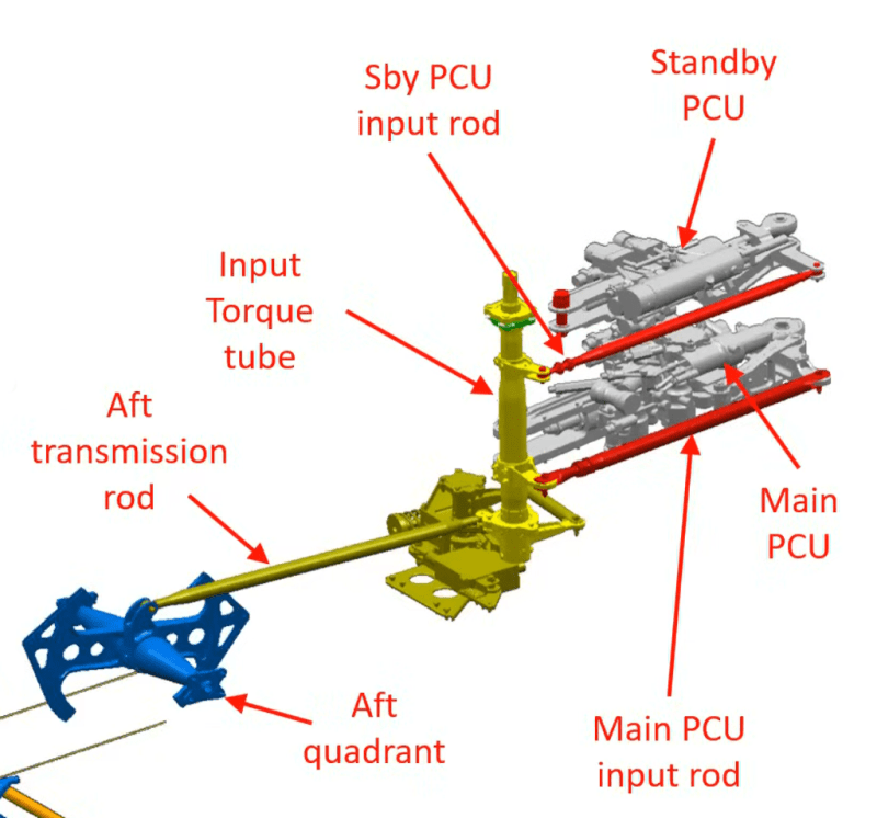
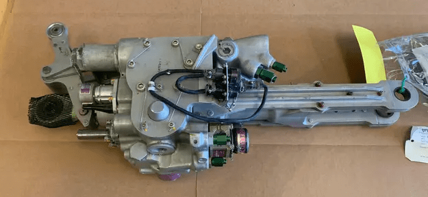
1. replace the main PCU as a likely cause
2. identified damaged bearing in the forward end of the upper input control rod (of the main PCU)
3. installed new upper input control rod
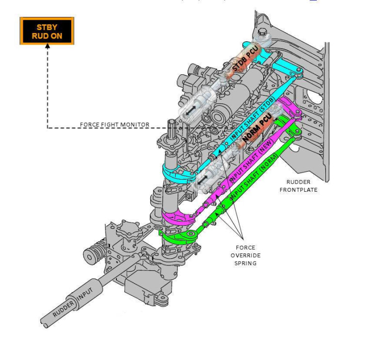
4. identified additional structural damage to the rudder system in the area surrounding the standby PCU bracket

This suggests that rather than doing a thorough initial investigation, they jumped to initial conclusions and chased their tail, only finding subsequent damage because they couldn't adjust the new components. This seems like a good way to miss critical issues.

The failure of the standby PCU bracket as the rudder system pressed against it could be consistent with the bearing damage on the input control rod if the rudder slammed hard over and pulled hard on the control rod at the same time. However, the bracket was significantly deformed and any damage at the other end of the system would have to match the amount of deformation. Is there more identifiable damage in the linkage? OTOH, if the bearing was damaged, were the multiple main and standby systems sending/receiving competing signals? How did the standby bracket deform while the main PCU attachment remained unscathed?

Just asking for some very busy friends.

 
In the earlier picture you posted it looks like the force that caused the failure was in the 10 o'clock direction. You can see shiny metal in that quadrant in the upper bolt holes with the bolts removed. The lower piece appears to have broken in the 5-6 o'clock regions. There is buckling in the web as the top of the comment tried to bend to the left and the bottom left was still secured.

I stand by my completely unsupported speculation that the tail wasn't backed into something, just a little bit. If they hit it square on, maybe it was stiff enough that it wouldn't damage the outer sheet metal.

This is what the framing looks like on a boat when we bump into a larger object such as a ship or the earth.
 
Wondering if it's been subjected to a flight upset recovery.

Boeing pilots for years were taught to recover using rudder to lift the wing. They only started telling pilots not to do cycle control inputs after the tail fell off an airbus after 911.

I have no clue if the rudder system on 737 has a travel limit depending on phase of flight.

Ours gets automatically limited by reducing the full travel of pedals to only give the max the limitations allow.

 
-1x-1_xes6nc.jpg


Hokkie is right this is the scope of what gets delivered.

Looks to me that the bracket is part of that and they just connect to the rudder.
 
So if I'm starting to understand the system, the standby PCU is one that the pilot can elect to turn on. It lacks protection from hitting the stops as the main PCU has so a gust of wind can throw the rudder from one extreme to the other and in such an event, the bracket can absorb all or most of the punishment, as can any other component in the many linkages. That makes sense now.

However, when the aircraft is parked and powered down, what determines the engagement of one system or the other. Is it just the last one on? What confidence can a pilot ever have that critical and hidden components haven't sustained damage while the aircraft is unattended?

Another thing that comes to mind is that once the bracket was deformed, would that lead to binding of the system or is there enough freedom of movement in the piston and its connections? Perhaps it could prevent the rudder from moving to one extreme as it no longer has as much extension.

Thanks for listening.
 
"Looks to me that the bracket is part of that and they just connect to the rudder."

Part of what? The PCUs are installed in the vertical stabilizer; nothing to do with the fuselage.

"Boeing pilots for years were taught to recover using rudder to lift the wing. They only started telling pilots not to do cycle control inputs after the tail fell off an airbus after 911."

The tail separated from the Airbus because Airbus has a flawed human factors design that allows full stop to stop movement with reduced pedal movement. The more critical it is not to slam the rudder back and forth the easier Airbus makes it for pilots to do so. Airbus pilots are expected to not overstress the vertical stabilizer via training.

Boeing pilots get accurate feedback; full pedal movement is always full allowable pedal movement.
 
They are in the bottom section behind the pressure rear bulkhead. Which is in the picture.

Zero clue about proper Airbus or Boeing old school
rudders.

Do know where that lot is on a 737. It used to need lifting gear to get it out of the rear bay with a team of 10 technicians.
 
"They are in the bottom section behind the pressure rear bulkhead"

Since there is continuing abuse of pronouns here, I have to guess you are referring to the PCUs. Proper use of proper nouns is better for clarity.

No, the PCUs are not behind the pressure rear bulkhead. The pressure bulkhead is roughly 5 feet lower than the PCUs are.

What is behind the rear pressure bulkhead is the horizontal stabilizer trim drive; neither are shown in the photo below.

Is it necessary to add even more labels?
Rudder_Pieces_wppee4_w5vxmu.png
 
As I haven't done type rating on one I have no reason to know how they do it on a 737. Or on an A320.

Must be confusing it with the elevator jack screw setup.

Still think a flight upset might be in the picture.


Back
Top