Continue to Site

Eng-Tips is the largest engineering community on the Internet

Intelligent Work Forums for Engineering Professionals

  • Congratulations IDS on being selected by the Eng-Tips community for having the most helpful posts in the forums last week. Way to Go!

Bolted Cover Plates 6

Status
Not open for further replies.

CDLD

Structural
May 20, 2020
218
Hello,

We have an existing galvanized beam we are reinforcing partial length with cover plates and we are connecting it with bolts rather than welds.

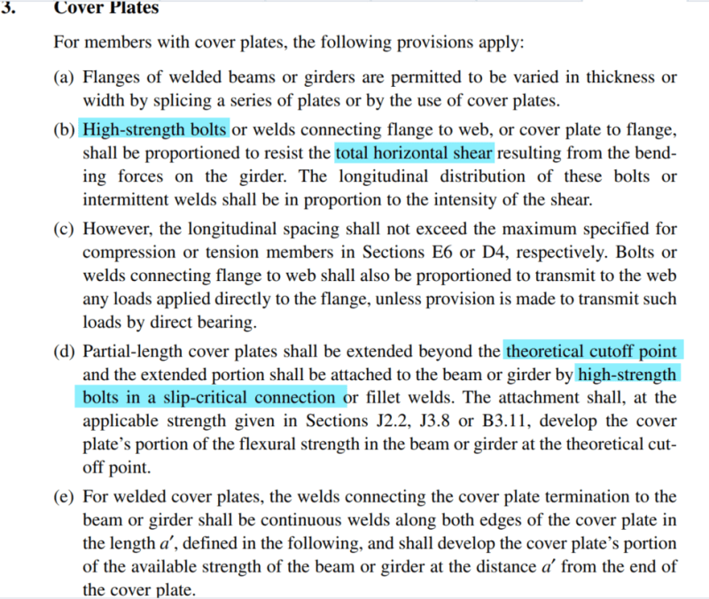
AISC states that slip critical bolts are required to develop the force at the theoretical cutoff points but does not explicitly state SC bolts are required for shear flow.

My interpretation is that slip critical bolts are required at the ends of the cover plate but the interior bolts used for shear flow do not need to be slip critical - Agree?
Screenshot_2024-03-22_100512_qtefyi.png
 
Replies continue below

Recommended for you

Though I 'm not familiar with the AISC spec, your interpretation of that section appears to be correct. However, if some of the bolts in the cover plate need to be SC, and they all need to be high strength, there would seem to be little advantage to making only some SC. With only the ends SC, I don't believe you can count on the cover plate to provide additional stiffness for deflection control or any fatigue resistance. There's also the issue of possible installation errors (do you have adequate QC to ensure all the bolts that need to be fully tensioned actually get fully tensioned?)
 
There are 5 beams 36 ft long that are being reinforced, I would argue that the savings may be worthwhile.
The drawings are currently issued with all bolts SC, I'm just looking back at it now wondering if I could have done it differently.

BirdgeSmith said:
With only the ends SC, I don't believe you can count on the cover plate to provide additional stiffness for deflection control or any fatigue resistance.
If AISC does intend to say that the bolts for shear flow do not need to be SC, then I believe your statement to be incorrect (at least for the deflection part). if you can count on the plate for strength, you can count on it for deflection.
 
I see where you are coming from about deflection.
I have my doubts about using standard bolts for shear flow and wonder if AISC's statement was in error.

I assume your position on the deflection has to do with the plates slipping to engage the bolts.

To me it doesn't make sense to use slip critical at ends and standard bolts at the interior. I don't understand how the interior bolts would engage if the ends of the plate are restrained from slip; but this seems to be what AISC is saying.

Just curious if anyone has any insight.
 
I assume your position on the deflection has to do with the plates slipping to engage the bolts.

Correct. For bridge girders, we don't do much in the way of cover plates, and pretty much all of our bolts are fully tensioned using tension controlled (AKA twist-off) bolts. The closest analogous situation I'm familiar with is steel girders composite with a reinforced concrete deck. For those, if we don't have shear studs over the interior supports, we aren't allowed by the AASHTO spec to consider the deck, or the rebar in the deck, as part of the section for fatigue resistance, deflection, or strength, even though there are extra shear studs at the ends of the reinforcing bars to transfer the force to the top flange of the girder.

To my way of thinking, the bolts that aren't SC shouldn't be assumed to do anything until the strain in the flange reaches the point where the bolts engage in bearing on the side of the bolt hole, which most of them would, if the beam is stressed to its strength limit state. However, until it reaches that strain level, the beam reacts as if those bolts aren't even there. If you had no bolts between the SC bolts at the ends, would you consider the cover plate fully effective as part of the section?
 
To me it doesn't make sense to use slip critical at ends and standard bolts at the interior. I don't understand how the interior bolts would engage if the ends of the plate are restrained from slip; but this seems to be what AISC is saying.
The interior bolts wouldn't engage until the slip force is exceeded.
 
BridgeSmith said:
The interior bolts wouldn't engage until the slip force is exceeded.
Exactly my point!
 
If a splice is designed as slip critical I don't see why you wouldn't also design a cover plate the same.

I also believe SC is for fatigue performance, reduced deflections and resistance to loosening under impacts or vibrations etc.

Turn of nut method is pretty typical in my area. I have not seen contractors complain about it.

 
Turn of the nut is probably not as accurate as a direct tension indicator (tension indicating washer). Both can be quite a bit of work for the inspector, unless one of the 'squirter' type DTI's is used.

The twist-off type bolts are easy for both installer and inspector, but requires the specialty tool. If the installer has one, I would not consider changing the contract - just have them tension them all. It won't even slow them down.
 
The cost saving is not worth the possibility of a screw up. The use of slip critical bolts throughout the length of the cover plate would be a more sensible engineering decision.
 
Yes, slip critical for all bolts. Enough to ensure there is good shear flow. If you want to reduce bolting you could consider fewer bolts in areas where lower shear flow is required.

Non slip critical bolts are essentially doing nothing. (Well they can still transfer shear up until they slip, but unless installed as slip critical then you can't quantify this so I wouldn't count it.)

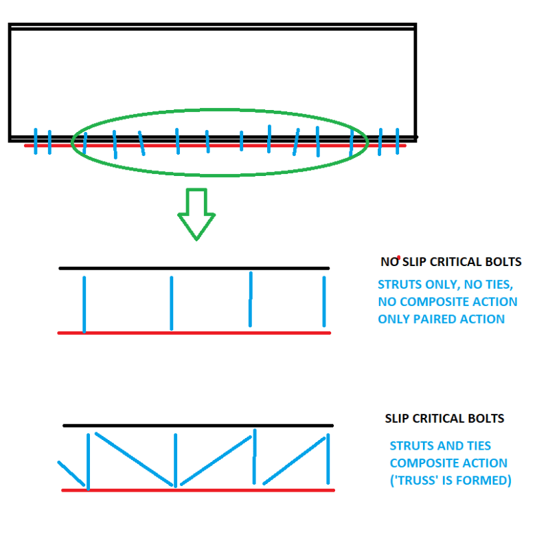
This might be a pretty simplistic and obvious explanation. But it is how I like to break things down in my head if I ever end up scratching my head too hard regarding shear flow. I break beams up into trusses. Or in this case break the flange and cover plate up into a truss. I then chase the load paths.

Here is a PAINT drawing to go with my simple analogy.

temp_fp7jkk.png
 
I don't think that sketch is an accurate representation of shear flow. Whether the bolts are SC or not, there are still only horizontal components of resistance being provided. However, at the plane between the plate and the beam, you are only resisting shear (which does have vertical components), so the strut and tie sketch isn't really appropriate anyway. The question is how much deflection you can live with, without failure. I would just email the AISC solutions centre, they are very good about providing answers, but it seems odd that this would be an unintentional mistake. My conjecture is that at ends of the cover plate (where it is no longer needed), the strains required to engage the bolts would probably cause undesirable deflections and are also less likely to occur before the beam is overloaded - think of a simply supported beam under uniform load, strains are greater at mid span and go to zero at support, so a cover plate at the ends may never be engaged.
 
canwesteng said:
I don't think that sketch is an accurate representation of shear flow. Whether the bolts are SC or not, there are still only horizontal components of resistance being provided. However, at the plane between the plate and the beam, you are only resisting shear (which does have vertical components), so the strut and tie sketch isn't really appropriate anyway. The question is how much deflection you can live with, without failure. I would just email the AISC solutions centre, they are very good about providing answers, but it seems odd that this would be an unintentional mistake. My conjecture is that at ends of the cover plate (where it is no longer needed), the strains required to engage the bolts would probably cause undesirable deflections and are also less likely to occur before the beam is overloaded - think of a simply supported beam under uniform load, strains are greater at mid span and go to zero at support, so a cover plate at the ends may never be engaged.

I believe there is a misunderstanding here. From my perspective there absolutely is vertical and horizontal components of resistance being provided by slip critical bolts. The friction from the slip critical nature is a horizontal component and the vertical is provided by bolt tension or direct bearing compression between the plate and the flange.

In the absence of any intermediate bolts (slip critical or not) then then yes you would lose your vertical component of resistance as the plate would hang loose. But that isn't what we are talking about here.
 
There's no vertical or horizontal component being provided by SC bolts that snug tight bolts don't also provide, only instead of friction the shear resistance is provided by bolt shear. In either case it doesn't align with the truss analogy.
 
canwesteng said:
There's no vertical or horizontal component being provided by SC bolts that snug tight bolts don't also provide
Agreed with the vertical aspect. Hence my truss analogy picture showing vertical struts. But disagree with the horizontal aspect:

canwesteng said:
only instead of friction the shear resistance is provided by bolt shear. In either case it doesn't align with the truss analogy.
But as has been pointed out by others, bolt shear (more accurately bearing) wouldn't occur with the expected differential deflections. You need to have significant ~1-2mm of movement before a bolt in bearing approaches capacity.

I hope my above points might have fully explained my initial post such that we are now in agreement. But if not I'll probably just let this slide as a difference of viewpoint. [smile]
 
If the tension at the midspan of the cover plate is resisted by the slip critical shear value of precisely the correct number of bolts each side of midspan, spaced as required by beam shear, then from a theoretical point of view, every bolt must be slip critical. There is no theoretical justification for using non-S-P bolts anywhere.
 
I feel that there is some theoretical justification for mixing bolt types.

1) The bolts used to develop the reinforcing past the cutoff point are mission critical for strength because:

a) They must deal with a concentrated uptick in horizontal shear demand (MQ/I).

b) Fastener redistribution is unavailable on the side of the development bolt group where the reinforcing is discontinued.

Interior fasteners can avail themselves of some redistribution without compromising ULS capacity.

I see this as somewhat analogous to how retreat the anchorage of rebar past the points of maximum moment and bar cutoff locations.

2) My assumption is that the non-SC bolts would still be pre-tensioned bolts. The differences between SC and pretension are primarily a) faying surface prep and b) inspection. As such, the pre-tensioned bolts can be expected to behave quite similarly to the SC bolts from the perspective of serviceability.

Whether or not it makes practical / economic sense to mix SC and pre-tensioned bolts when some of the bolts on each beam would need to be inspected and prepped differently anyhow is another matter. That said, if a contractor asked me to consider mixing systems with some real savings up for grabs, I would allow that barring concerns for fatigue etc.
 
I guess I thought it was implied but just so it is here...slip critical design is at service loading (in my area). Hence the fatigue and deflection implications etc.
If you don't design it as slip critical it wont act that way at service loads.

If I remember correctly, galv coating has a lower slip factor than uncoated mill scale steel. So you may need a bit more boltage.
 
I agree with those who suggest using slip critical bolts throughout.
For galvanized steel the coefficient of friction should be taken as 0.175, half that of bare steel 0.35.

Ooo eee ooo ah ah ting tang walla walla bing bang
 
Status
Not open for further replies.

Part and Inventory Search

Sponsor