Continue to Site

Eng-Tips is the largest engineering community on the Internet

Intelligent Work Forums for Engineering Professionals

  • Congratulations GregLocock on being selected by the Eng-Tips community for having the most helpful posts in the forums last week. Way to Go!

BUCKLING FEA - The case of a 'pinned' base plate 4

Status
Not open for further replies.

human909

Structural
Mar 19, 2018
2,007
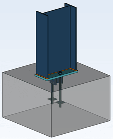
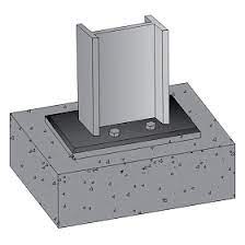
One thing that I've often been curious about is the buckling behaviour of a nominally pinned column under compression with a typical 'pinned' base plate.

Examples:
temp_lpzvch.jpg
temp2_zsevhq.png


For both of these I would consider these as 'pinned' connection and model them as such. Thus I'd would get zero moment transfer and effectively length of 1 if top of the column is braced but with no rotational restraint. As I understand it this is a pretty typical analysis approach under most codes and in most jurisdictions.

My question is:

Is this overly conservative? Would the compression and flat base plate not provide a degree of fixity and thus improve the critical buckling load? Here I define here a baseplate that is resting on a foundation but not restrained from uplift as a SEPPERABLE BASE PLATE.


It would surprise me if there isn't already plenty of literature on this matter. But I've never seen it. So I'd though I'd test it. And since I don't have a test laboratory at hand I figure I'd use FEA.

TEST APPROACH
-Non-linear plastic FEA analysis using NASTRAN
-Tri linear model of stress-strain curve used
-Iterative approach to converge on buckling solution (NASTRAN does have non-linear buckling analysis but not nonlinear PLASTIC buckling analysis)
-An additional lateral load of 1% of axial load was added to trigger the buckling. (This value is arbitrary but considered reasonable and conclusions not sensitive to this.)

TEST DETAILS
-Steel section: HEB160 S275 (EUROPEAN STEEL)
-Section length: 6600mm
-Minor axis translationally fixed, translationally fixed at the top, rotationally free.
-Base plate modelled in 3 ways; perfectly pinned; able separate but not slide AND; rigidly connected to foundation.
-Nominal mesh size - 50mm

CODE BUCKLING LIMIT:
Ncx = ~780kN (without any capacity reduction factor, both codes AS4100 and Eurocode within 2%)

FEA RESULTS
PINNED: Ncx = ~800kN
BASE PLATE (with sepparation): Ncx =~1150kN (equivalent le = 0.83)
BASE PLATE (RIGID): Ncx =~1150kN (equivalent le = 0.83)

As can be seen no discernible difference (<1% tolerance) between the rigidly connected base plate and a base plate with no uplift restraint.

CONCLUSION
In some/many circumstances it is not unreasonable to consider a typical column and base plate arrangement as 'fixed' for consideration of its buckling effective length. Without doing exhausting further testing I would suggest that this is reasonably representative for columns of 'intermediate slenderness' where inelastic buckling dominates.


ADDITIONAL TESTING
I was a little perturbed by the lack of discernible difference between a rigidly fixed base plate and one that is able to separate from its support. I hypothesised that this was due to inelastic buckling dominating before any appreciable rotation could occur at the base. This was tested by doubling the length of the HEB160 to 13200mm. To summarise this additional testing:
PINNED BASE = 275kN (Unreduced capacity in code 250kN)
BASE PLATE ON SURFACE = 460kN (equivalent le = 0.77)
FIXED BASE PLATE = 500kN (equivalent le = 0.74)

It was satisfying to see that for more slender columns the back calculated effective length approached the theoretical Euler elastic theoretical length. It was also satisfying to confirm that a fully fixed base base does exhibit better performance (as expected) compared to a separable base plate.


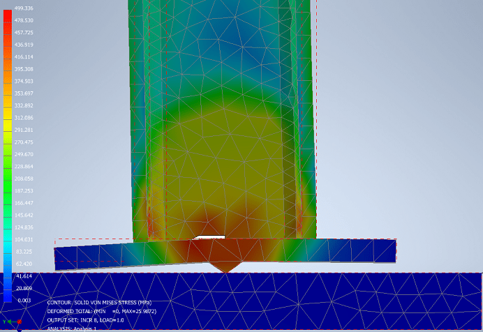
And here is a pretty FEA picture to keep everybody happy:
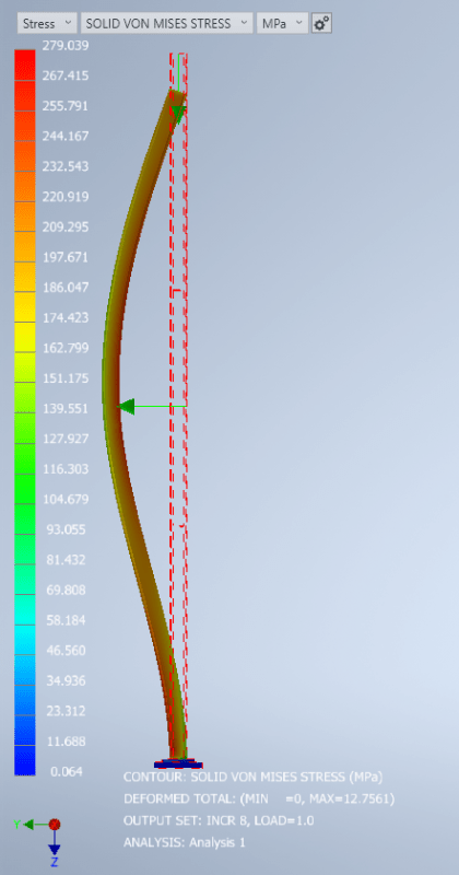
temp3_mzr32q.png
 
Replies continue below

Recommended for you

centondollar said:
... is related to overturning...... - not restraining rotation.
you can't arrest overturning without restraining rotation. The presence of axial compression in the system restrains a portion of rotation, the same principle is used with great success in the post-tension industry.
 
"you can't arrest overturning without restraining rotation."

The overturning equation doesn't require restraining rotation in the sense that there would be a rotationally stiff joint in a beam-baseplate-footing detail. Overturning is prevented as long as the footing doesn't topple over, but the footing-beam joint does not need to restrain any rotation for that to happen. You can have a completely pinned column and still find that the footing is toppling due to overturning moment.

" The presence of axial compression in the system restrains a portion of rotation, the same principle is used with great success in the post-tension industry."
Base plates connected through a large footing into rock by post-tensioning tendons were not the topic of discussion. If such are applied, they will act as bolts, and as I previously mentioned, sufficient numbers of and spacing of such bolts can create a force couple that restricts rotation of the column-footing joint.

The axial compression in the beam itself does not create a stiff joint at the beam-footing interface. To achieve that, the beam-footing joint must be restrained from rotating, and that cannot be achieved by bearing on the compression face of a base plate placed loosely (or with bolts close to beam N.A.) on concrete.
 
(chapter 4)
(chapter 6)

Notice the "typical moment connection" recommendations: pocketed base (rotation restrained by significant embedment, creating a force couple of column-concrete compressive bearing forces), base plate with wide bolt spacing, and base plate with wide bolt spacing and stiffeners to prevent local failure of beam.
 
centondollar - I don't think anyone is arguing that you can have a rigid base plate without bolts. The question is: how does the inherent fixity in typical bases impact the actual critical buckling load of a column?

If I design a column for gravity load only, put a 1/2" plate under it and 4 bolts in a simple pattern, that connection will be assumed in a global analysis to be a pin. But we all know it's NOT a pin. It has fixity. It's not going to be stiff enough to be considered a moment connection at significant levels of loading, but there is fixity there. That fixity will prevent rotation of the column base enough to increase the critical buckling load some, though not as much as it would be increased for a true moment connection.

And even if I don't put bolts in it, it will resist small moments as long as there is no net tension in any portion of the column. As Celt said, this principle is used in post-tensioned concrete. It's also what makes unreinforced masonry work. If you look at the capacity of a URM wall, the moment capacity increases with increased axial compression because it reduces the net tensile stress. So long as we never see net tension, the base of the column will not rotate. Now this is an extreme case and, in the case of buckling, would likely have a negligible impact since the resistance to rotation is derived from the compression in the column and the buckling load is also roughly derived from the compression in the column through an initial geometric imperfection.

 
"And even if I don't put bolts in it, it will resist small moments as long as there is no net tension in any portion of the column. As Celt said, this principle is used in post-tensioned concrete."
You'll have to explain this in more detail. If you are referring to decompression due to P/A + M/W, that has nothing to do with rotational restraint at a column-footing connection loaded by moment, axial force and shear force.

"So long as we never see net tension, the base of the column will not rotate."
The base of the column will rotate as long as its connection to the footing is insufficiently stiff. A fillet weld will not prevent rotation, nor will a fillet weld and a base plate with poor bolt arrangement.

"Now this is an extreme case and, in the case of buckling, would likely have a negligible impact since the resistance to rotation is derived from the compression in the column and the buckling load is also roughly derived from the compression in the column through an initial geometric imperfection."

The resistance to the rotation is a property of the joint, not of the column or the forces in it. If you apply lateral load (e.g., wind) to a pinned column causing it to bend, it will rotate freely (zero moment at the footing) regardless of how much axial load you apply. Ergo, the point of inflection of the buckling mode (found by solving the non-linear system of equations and not by eigenvalue analysis) will be at the footing. Ergo, the base will be pinned, not stiff.

Furthermore, the Euler buckling load involves only flexural stiffness, length and boundary conditions. The boundary condition of the details you show in the first post is pinned.
 
centondollar - you are completely missing the point of this entire exercise. You might want to re-read the first post, and all of the other posts that are trying to explain this to you. We all know what a fixed/rigid column base connection looks like. We all know that human909's model is not a fixed/rigid base. That is the intent - to examine the actual behavior of a real-world "pinned" base and the effect it has on the column capacity.
 
centrondollar you seem to be extremely stuck on multiple wrong ideas here. Most I'll give up trying to correct you. I and others have done our best.

centrondollar said:
You are not solving the Euler buckling load when running a non-linear FEA, and the energy considered when deriving the Euler bifurcation buckling formula is bending energy and external load energy, both of which involves only lateral displacement and its derivatives of various orders.
Well I AM solving the analysis based on compression as the variable. That is the dominant force input into the model and the limit is considered the critical buckling load. In the case of non-linear elastic analaysis the solution exactly matches the Euler theory. In the case of plastic analysis it doesn't. Both as expected.

Oh and in case anybody was wondering. To create a 'pinned' base connection I did not wish to change the boundary conditions on the full model as I wanted to keep these consistent. Instead I provided a localised support between the base plate and the fixed foundation. As expected this behaved essentially like a pin which could be seen with the results matching Euler buckling behaviour.
temp4_bfweey.png
 
Centondollar said:
Without bolts, the bending of the column will not be restrained at the joint,

Yes this is ordinarily the case, it’s just that in this case we have a load in the column which provides that restraint across the joint that the bolts would normally provide.
 
Human909,

That baseplate looks pretty big. What size did you use in the initial assessment? Have you run the analysis with baseplate matching the column size? I’m curious how wide the column base needs to be to provide effective fixity.

What size are the prefabricated columns and baseplates?
 
Could you please show the "rigid" boundary condition? A plot of the contact stress (plate-concrete), von Mises stresses and the rotation would be nice, since those could reveal the physical correctness of the model.

"Well I AM solving the analysis based on compression as the variable. That is the dominant force input into the model and the limit is considered the critical buckling load. In the case of non-linear elastic analaysis the solution exactly matches the Euler theory. In the case of plastic analysis it doesn't. Both as expected."

What happens leading up to the critical buckling load (without bolts or with a pinned bolt arrangement) is that the column will rotate with the baseplate, thus not restraining rotation (dy/dx = 0 at x=0). This is evident from an intuitive understanding of what is required to create a rotational stiffness in a joint. You need a force couple to create rotational stiffness (which, once again, in this case is defined as zero absolute and relative rotation of the beam-to-footing connection), which bearing on part of the plate does not achieve.

Tomfh,
"Yes this is ordinarily the case, it’s just that in this case we have a load in the column which provides that restraint across the joint that the bolts would normally provide."

When close to the "buckling load" (fast increase in deflection), that clamping effect will be lost. As soon as the plate loses contact somewhere along the plate-concrete interface, rotation of the column will be free, indicating a pinned connection.

I'm just not quite convinced about this analysis and the boundary conditions employed in it. Nobody would use large bolt spacing and bolt sizes to create moment joints if it were achievable with minimal bolting.
 
centondollar said:
Nobody would use large bolt spacing and bolt sizes to create moment joints if it were achievable with minimal bolting.

Nobody is saying you can. We're saying that simplified models used in practice are conservative and do not represent the actual mechanics of many column base connections that are assumed to be "pinned."

The OP's specific question was whether or not it is, in some cases, too conservative.
 
The analysis results put the axial stress in the neighbourhood of 150-210 MPa for the pinned and restrained cases respectively. So the columns are slender without being extremely slender. Not surprising then that the base plate isn't lifting off, which is when the bolt positioning becomes interesting/critical in this case.

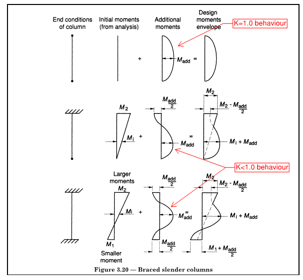
Moving from Euler elastic buckling to real non-linear behaviour, you need to be able to develop reverse curvature of the non-linear moments at the ultimate limit state. If the column were very slender, the non-linear moments would be large when the axial force is small. Even in that case, there would be some improvement compared with true pin because of the offset axial reaction, but at some point it won't be the full benefit of fixity. Without solving it, my gut feel is that a reasonable approximation could be found from fairly simple calculations.

Clip below from BS 8110 to illustrate the non-linear moment in restrained-end 'buckling'. Note that 'M_add' isn't the same value in each case, and M_add/2 is an approximation.

BS8110_BracedSlender_k1wr7i.gif


Code compliance-wise, depends on the applicable code. Considering something fixed may trigger minimum robustness requirements which would need to be satisfied in the absence of the axial load. I believe these minimum robustness requirements typically apply on top of advanced analysis, ie you can't just say the analysis didn't require moment capacity from the bolts, because the robustness requirements are meant to cover the unknown/unquantifiable. Steel to concrete is a grey area though, in the gap between two codes.
 
Tomfh said:
Human909,

That baseplate looks pretty big. What size did you use in the initial assessment? Have you run the analysis with baseplate matching the column size? I’m curious how wide the column base needs to be to provide effective fixity.
Good point. I'm rerunning it as I type. And I'll update this post when I'm done.

Tomfh said:
What size are the prefabricated columns and baseplates?
The base plates used were 300x300x30mm. I agree these are pretty big for the column size I believe this is due to them being a standard baseplate for this OEM. The for example even if at HEB240 or 260 then same baseplate would likely be used. I don't believe the base plate width would make much difference for these members of intermediate slenderness as plastic buckling dominates and thus you don't need much rigidity in the base.

As far as the demands on these columns. Theses columns are under almost exclusively axial compression. In certain circumstances uplift can become dominant so bolts to restrain uplift are required. Shear loads are well distributed so the shear loads on anchors are low.

{RESULTS}

The calculations were run again for 6600mm HEB160. A base plate of 180x180x10mm was used which I would describe as on the small and thin side of things. There was no discernible difference between the critical buckling loads. (+/- 1%). As was hypothesised I believe that since plastic buckling dominates, a slight reduction in base stiffness has no effect.

I would expect that as the slenderness ratio increases the size plate might make a difference. Likewise it is fairly self evident that for base plates less than the column width the behaviour will become more like a pin. At this stage I don't have the time to fully delve into this, but I believe the last two comments should be self evident.

 
Forgot to mention: Load < half of yield seems like it would be a threshold value, or close to one. Otherwise the (+M*y/I) causes compression yield before the (-M*y/I) causes lifting on the other side.
 
steveh49 said:
but at some point it won't be the full benefit of fixity
Correct. Which is supported by my additional results where I found that additional fixity did improve the capacity by ~10%:
BASE PLATE ON SURFACE = 460kN (equivalent le = 0.77)
FIXED BASE PLATE = 500kN (equivalent le = 0.74)

steveh49 said:
Code compliance-wise, depends on the applicable code. Considering something fixed may trigger minimum robustness requirements which would need to be satisfied in the absence of the axial load. I believe these minimum robustness requirements typically apply on top of advanced analysis, ie you can't just say the analysis didn't require moment capacity from the bolts, because the robustness requirements are meant to cover the unknown/unquantifiable.
As you say it depends on the applicable code. Though in many cases I believe you can get around this by considering the connection as PINNED for the purposes of moment transfer but as fixed for the purposes of calculating effective lengths. Many codes have a fair bit of liberty allowed for the engineer to calculate an effective member length in a rational analysis approach as opposed to a prescribed codified approach. Thought your mileage may vary depending on the code.

(Of course none of this is me advocating finding loopholes in codes. As I emphasised in my first post I'm pretty happy with the simple and conservative approach of treating it as pinned to calculate effective length.)


steveh49 said:
Forgot to mention: Load < half of yield seems like it would be a threshold value, or close to one. Otherwise the (+M*y/I) causes compression yield before the (-M*y/I) causes lifting on the other side.
Yes. Inelastic behaviour is playing a decent part in the making this into a more complex problem. After all, the Euler buckling limit for this column is around 1562kN whereas the plastic buckling limit is ~1150kN.
 
human909 said:
Though in many cases I believe you can get around this by considering the connection as PINNED for the purposes of moment transfer but as fixed for the purposes of calculating effective lengths. Many codes have a fair bit of liberty allowed for the engineer to calculate an effective member length in a rational analysis approach as opposed to a prescribed codified approach.
The effective length concept is a result of the boundary condition, not a separate matter. If the joint is pinned, it transfers no moment and does not prevent beam rotation, leading to some effective length. If the joint is rigid, it transfers moment and prevents beam rotation, leading to some effective length. This is the first step in a rational analysis.

PS. Relying on clamping from axial force (keeping the entire plate fully compressed at all times) to achieve some measure of rigidity in the joint is not practical at all. You'll find yourself having to add weight to the structure to keep this clamping active for all load combinations. Also, your FEM model should show reasonable contact stress conditions and zero or near-zero absolute beam rotation for the "rigid joint without bolts" if it is correct.
 
centondollar said:
This is the first step in a rational analysis.
If that is your first step then I won't fault you for that. But please recognise that is not the only rational analysis approach. A nominally pinned base plate as discussed is actually not a pure pin, that should be obvious. Furthermore, the rigidity of the connection to the footing changes with axial load. This is the behaviour that is being analysed here. And the conclusions is that in this (an by extrapolation, many) circumstances this rigidity is more than sufficient for the boundary condition with regard to axial buckling behaviour to be considered as 'fixed',

centondollar said:
PS. Relying on clamping from axial force (keeping the entire plate fully compressed at all times) to achieve some measure of rigidity in the joint is not practical at all.
Actually it can be entirely practical. If the maximum demand on the column is axial then the maximum rigidity of the joint occurs at the same time as maximum demand. So you can safely rely on this effect. If my column is undergoing uplift then to be honest I really don't care about its axial compression capacity for that load combination.

This analysis shows that is is entirely justifiable to cater for a reduced effective length due to the behaviour of these nominally pinned base plates on a rigid foundation.
 
centondollar said:
If the joint is pinned, it transfers no moment and does not prevent beam rotation, leading to some effective length. If the joint is rigid, it transfers moment and prevents beam rotation, leading to some effective length.

In the simplified methods in use since before the benefit of computers to aid us in analysis, yes. It's also the tried and true method we all use. This is an exploration of actual behavior and validation of (what sounds to me) like a delegated or otherwise submitted design. human909 has himself said he doesn't advocate the use of this concept in design. Also, a lot of us work with existing buildings, and it's important to understand why buildings that "should have collapsed" actually haven't.

 
Thanks phamENG for the good summary.

And yes this is all about due diligence on a OEM supplied structure. To be specific it is a steel hopper type silo of around 1700m3. Treating the supporting columns as pinned either end gives results in a design capacity below the factored design loads. And given these are silos these structures will REGULARLY see the full unfactored live load. So it isn't like there is a huge headroom here.

On the flipside. This supplier would sell thousands of these items each year. Given they aren't failing left right and centre I have to consider the fact that their calculations aren't unconservative and I am the one being overly conservative. Hence my investigation.

For good measure, as I said above, I did give the supplier and RFI and would like to see their justification.
 
Even if there is a large axial compression in the column, a lateral load will cause the column to bend. If this bending is not restricted at the column-base plate-footing joint with widely spaced bolts or a massive concrete pour encasing the end of the column, it will cause a rotation, i.e., a pinned joint situation.

If the column has practically zero bending moment, the situation is of course entirely different, but I doubt that a hopper silo column (with significant lateral tank water sloshing effects due to wind and seismic effects) does not bend.

Remember that in e.g., post-tensioning, the axial compression (-P/A) contribution to resistance is small. If you want precompression from axial loads to "glue" the base plate onto concrete without significant bolting, you have to ensure that axial load is very eccentric and always located on the correct side of the column (to get +- M/W effect decompressing column and base plate at all times). Both of these are impossible: the eccentricity is theoretical and includes code-prescribed bow imperfections etc., while wind and water sloshing can act in any direction.

I'm still not convinced by the physical arguments, but seeing those contact stress plots and rotation plots for the supposedly rigid connection without bolting would perhaps sway me.
 
Status
Not open for further replies.

Part and Inventory Search

Sponsor