Continue to Site

Eng-Tips is the largest engineering community on the Internet

Intelligent Work Forums for Engineering Professionals

  • Congratulations GregLocock on being selected by the Eng-Tips community for having the most helpful posts in the forums last week. Way to Go!

BUCKLING FEA - The case of a 'pinned' base plate 4

Status
Not open for further replies.

human909

Structural
Mar 19, 2018
2,007
One thing that I've often been curious about is the buckling behaviour of a nominally pinned column under compression with a typical 'pinned' base plate.

Examples:
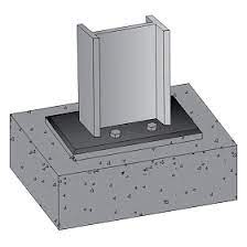
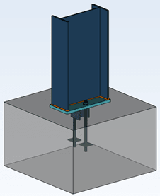
temp_lpzvch.jpg
temp2_zsevhq.png


For both of these I would consider these as 'pinned' connection and model them as such. Thus I'd would get zero moment transfer and effectively length of 1 if top of the column is braced but with no rotational restraint. As I understand it this is a pretty typical analysis approach under most codes and in most jurisdictions.

My question is:

Is this overly conservative? Would the compression and flat base plate not provide a degree of fixity and thus improve the critical buckling load? Here I define here a baseplate that is resting on a foundation but not restrained from uplift as a SEPPERABLE BASE PLATE.


It would surprise me if there isn't already plenty of literature on this matter. But I've never seen it. So I'd though I'd test it. And since I don't have a test laboratory at hand I figure I'd use FEA.

TEST APPROACH
-Non-linear plastic FEA analysis using NASTRAN
-Tri linear model of stress-strain curve used
-Iterative approach to converge on buckling solution (NASTRAN does have non-linear buckling analysis but not nonlinear PLASTIC buckling analysis)
-An additional lateral load of 1% of axial load was added to trigger the buckling. (This value is arbitrary but considered reasonable and conclusions not sensitive to this.)

TEST DETAILS
-Steel section: HEB160 S275 (EUROPEAN STEEL)
-Section length: 6600mm
-Minor axis translationally fixed, translationally fixed at the top, rotationally free.
-Base plate modelled in 3 ways; perfectly pinned; able separate but not slide AND; rigidly connected to foundation.
-Nominal mesh size - 50mm

CODE BUCKLING LIMIT:
Ncx = ~780kN (without any capacity reduction factor, both codes AS4100 and Eurocode within 2%)

FEA RESULTS
PINNED: Ncx = ~800kN
BASE PLATE (with sepparation): Ncx =~1150kN (equivalent le = 0.83)
BASE PLATE (RIGID): Ncx =~1150kN (equivalent le = 0.83)

As can be seen no discernible difference (<1% tolerance) between the rigidly connected base plate and a base plate with no uplift restraint.

CONCLUSION
In some/many circumstances it is not unreasonable to consider a typical column and base plate arrangement as 'fixed' for consideration of its buckling effective length. Without doing exhausting further testing I would suggest that this is reasonably representative for columns of 'intermediate slenderness' where inelastic buckling dominates.


ADDITIONAL TESTING
I was a little perturbed by the lack of discernible difference between a rigidly fixed base plate and one that is able to separate from its support. I hypothesised that this was due to inelastic buckling dominating before any appreciable rotation could occur at the base. This was tested by doubling the length of the HEB160 to 13200mm. To summarise this additional testing:
PINNED BASE = 275kN (Unreduced capacity in code 250kN)
BASE PLATE ON SURFACE = 460kN (equivalent le = 0.77)
FIXED BASE PLATE = 500kN (equivalent le = 0.74)

It was satisfying to see that for more slender columns the back calculated effective length approached the theoretical Euler elastic theoretical length. It was also satisfying to confirm that a fully fixed base base does exhibit better performance (as expected) compared to a separable base plate.


And here is a pretty FEA picture to keep everybody happy:
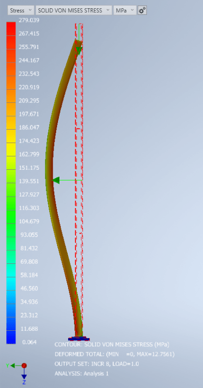
temp3_mzr32q.png
 
Replies continue below

Recommended for you

[banghead]

centondollar said:
I'm still not convinced by the physical arguments, but seeing those contact stress plots and rotation plots for the supposedly rigid connection without bolting would perhaps sway me.

Can you point us to the part of this thread where anyone has suggested this is a rigid connection?
 
centondollar said:
it will cause a rotation, i.e., a pinned joint situation.

Rotation doesn't necessarily mean the connection is "pinned". As with any type of connection, it is a rotational spring with a certain stiffness. The analysis above showed that this arrangement acts more like a rigid connection than a pinned one, although obviously somewhere in between.

centondollar said:
you have to ensure that axial load is very eccentric and always located on the correct side of the column

There is no reason the eccentricity can't change sides under alternating loads while maintaining the precompression required to ensure a rigid or rotationally stiff connection.
 
gusmurr said:
There is no reason the eccentricity can't change sides under alternating loads while maintaining the precompression required to ensure a rigid or rotationally stiff connection.

It would be interesting to see the results with the load eccentricity at the column face, then at 100mm past the column face, etc. Would it make a significant difference to the effective fixity of the base?
 
Tomfh, I think it would. My gut feel is that the more eccentric the load, the more the connection would act like a true pinned base.
 
I was curious to know how this would behave if we delete the anchor bolts altogether and just rely on the baseplate supported in compression only.

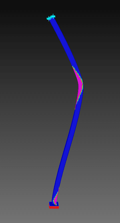
Initial out-of-straightness was taken as L/200 = 33 mm; elastic - perfectly plastic material was assumed with 275 MPa yield strength; stiff compression-only support under baseplate.
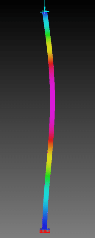
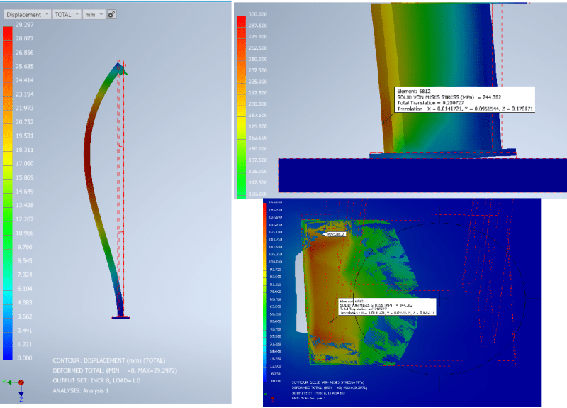
Below is showing the deformed shape for a load of 800 kN, close to the point of buckling. You can see that the base is fairly well vertical.
1_bavscc.png


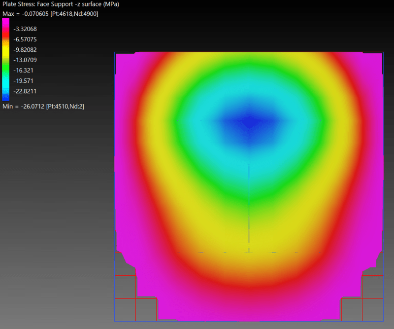
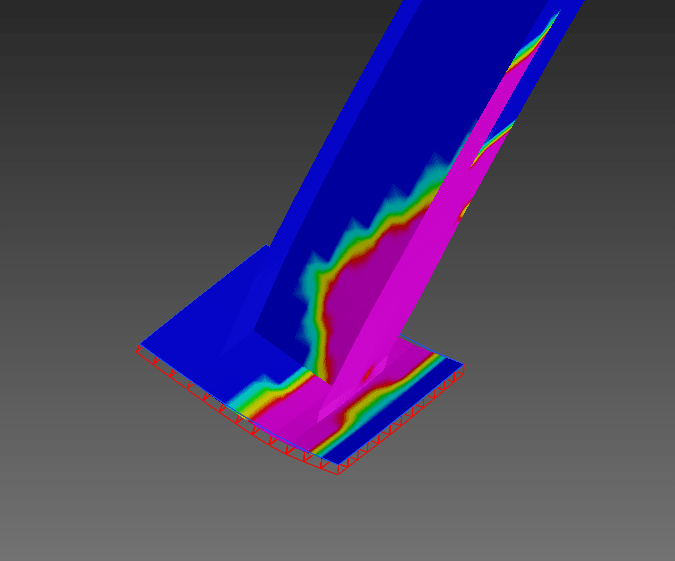
Contact pressure under baseplate at 800 kN load is shown below, indicating almost full contact.
2_izvd5r.png


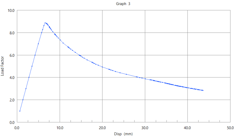
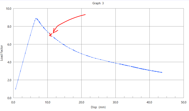
The ultimate buckling load is about 887 kN, which is quite a bit more than the code-based buckling load of 780 kN stated by OP, and implies an effective length factor in the order of 0.9. No doubt with anchor bolts, this would be closer to 0.8 as others have stated. The anchor bolts do not see any tension until well after the peak load is reached, so the 0.9 effective length factor would probably apply even if bolts were added in. Note that load factor of 1.0 below is equivalent to 100 kN force applied.
3_fy73ee.png


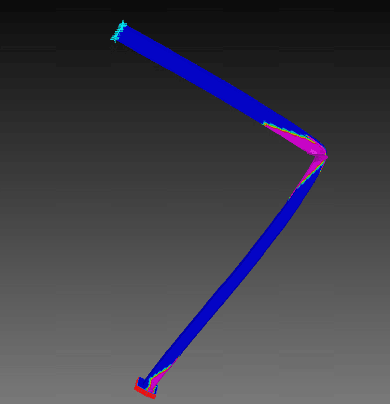
Even well past the peak load, the baseplate is able to provide almost enough rotational stiffness that a plastic hinge would form through the column there, but the bending strength of the baseplate itself seems to be limiting this. Below areas shaded in pink are showing the yielded regions (displacement scaled up 10x).
4_tfleum.png

5_aqf0ee.png


However ultimately the column forms a plastic hinge near its mid-height (displacements scaled up 10x).
6_pevj5g.png
 
@human / @guss

What's the deflection of the baseplate at the locations where the "minimally effective layout" anchor bolts would be? Essentially the center of the plate if using only two anchors as shown in human's OP photo #2. Ultimately, what would the tension load on the anchors be due to prying/rotation prior to column buckling (and beyond). Assuming 3/4" dia x 12" heff anchors I suppose. It looks like there is still compression under the plate at those anchor locations though, until post buckling - so, zero? If so, does this further the current theory regarding contact stresses under the column flange/web intersection being the primary reaction providing most of the "fixity", as it were?

It looks like the results here would be pretty sensitive to the column section properties? Shear deformation in the web specifically. But less so than baseplate properties which are variables in the joint stiffness?

(Note all of the above is considering the anchors do not have a standoff. I.e., tension only.)
 
@dold up until the point of buckling - zero upward deflection of the baseplate.

The middle part of the baseplate only begins to lift up where I've shown on the graph, so I guess the anchor bolts would not be engaged until this point is reached.

Capture_cmcmdk.png

Capture2_umaadv.png
 
Thanks gusmurr. For following up on this. I'd like to point out that my model also didn't have anchor bolts. (I did try having them in but didn't see any change in behaviour at the initial length.)

Thanks for providing the extra information regarding the contact patch. That is good work and something that I should have included.

If I get time I might see what my buckling behaviour is with that same imperfection as you used. I'd argue that a 33mm imperfection is pretty severe and likely accounts for the lower buckling loads that you have vs mine and vs code at an effectively length of 0.85.

dold said:
Ultimately, what would the tension load on the anchors be due to prying/rotation prior to column buckling (and beyond). Assuming 3/4" dia x 12" heff anchors I suppose. It looks like there is still compression under the plate at those anchor locations though, until post buckling - so, zero?
Yes. Zero load on the anchors. When I doubled the column length to 13200mm. I did notice a slightincrease in capacity between a truly rigid connection and the non anchored connection. So presumably there would be some uplift on the anchors bolts just prior to buckling. I haven't measured this. Also not that 13200mm long HEB160 is a ridiculously slender column.
 
human909, I agree the L/200 is a large imperfection. I think L/1000 is normally what is produced in practice and what the steel fabrication standard allows for. The L/200 was taken from AS 5100.6 4.10.5 and I believe also accounts for the effects of residual stresses in the hot rolled section (so it's an effective imperfection). I believe this approach tends to give somewhat conservative results. I'm sure that the real effective length factor is closer to 0.85.
 
gusmurr said:
Rotation doesn't necessarily mean the connection is "pinned". As with any type of connection, it is a rotational spring with a certain stiffness. The analysis above showed that this arrangement acts more like a rigid connection than a pinned one, although obviously somewhere in between.
In theory, a rigid connection has zero rotation. I didn't imply that reality is different, but the rotation should be negligible (close to zero) if the models shown in this discussion are to be considered accurate.

gusmurr said:
There is no reason the eccentricity can't change sides under alternating loads while maintaining the precompression required to ensure a rigid or rotationally stiff connection.
How do you suggest to change the side of the eccentricity in real time (required if precompression is to be ensured at all times)? It is not something you actively control during the life cycle of the column, and is composed of imperfections (residual stress, bow imperfection) which can act in at least two different directions (doubly symmetric columns) or in any direction (circular columns). There is no way to either accurately determine location of the eccentricity "e" and its effect " +- (P*e)/W " on the column.

dold said:
Can you point us to the part of this thread where anyone has suggested this is a rigid connection?
You can use "ctrl+F" and find a reference to a rigid connection in several parts of this thread, starting with the first post, to which I originally directed all my replies. I hope you're not being disingenuous.
 
Hi gusmurr,

For what it is worth, I tried you 33mm imperfection and got around 940kN buckling. That is more deviation that I would have expected, but not beyond the realm acceptability given the many differences in our models. I tried fiddling around with mesh sizing (reducing it) and the stress-strain curve (matching it to yours) and that dropped it to 920kN.

I don't think there is much to be gained in us chasing our differences further but I thought I'd try it out to see.

centondollar said:
You can use "ctrl+F" and find a reference to a rigid connection in several parts of this thread, starting with the first post, to which I originally directed all my replies. I hope you're not being disingenuous.
Centondollar you continue to demonstrate you have not grasped the concepts being discussed here. I apologise that I haven't been clear enough for you, though it does seem that I have been clear enough for most people to understand and participate in the discussion. Many have tried patiently to explain it to you but we have all failed. I'm not going to persist and I think most others are pretty close to giving up too.

PS. Dold was not being disingenuous. This discussion is NOT about rigid connection. The only time which we might have considered a rigid connections is as a comparison point to connection being discussed. (Which is often describe as pinned, but in actual fact is semi rigid with stiffness varying with axial load.)
 
human909 said:
Centondollar you continue to demonstrate you have not grasped the concepts being discussed here. I apologise that I haven't been clear enough for you, though it does seem that I have been clear enough for most people to understand and participate in the discussion. Many have tried patiently to explain it to you but we have all failed. I'm not going to persist and I think most others are pretty close to giving up too.
I grasp the concepts perfectly, but I do not agree on relying on a clamping from axial load to create a semi-rigid (or close to rigid) footing-column boundary condition. Furthermore, you have still not shown details of the semi-rigid calculations (contact stresses, von Mises stresses, rotation of plate and column), which makes me doubt your results. Plots of global buckling modes and a "pinned" calculation in which the concrete footing has zero stress (completely unrealistic) do not exactly demonstrate your claim that rotational fixity can be achieved without widely spaced bolts.

I have provided several good questions and suggestions, most left unanswered or ignored. It might be worth asking yourself why this detail is not used in industry. Are other engineers ignorant, or did you miss something in your model or in the underlying assumptions?

I want to reiterate that if the load direction changes (wind, seismic, sloshing) and if the magnitude and direction of eccentricity is uncertain (and not controllable in real-time), there can never be guaranteed precompression due to axial load in all or most parts of the plate. This is the most glaring issue in this "rotational stiffness without widely spaced bolts"-idea that you present.

human909 said:
PS. Dold was not being disingenuous. This discussion is NOT about rigid connection. The only time which we might have considered a rigid connections is as a comparison point to connection being discussed. (Which is often describe as pinned, but in actual fact is semi rigid with stiffness varying with axial load.)
The entire point of this thread has been to investigate how column-footing connection details and modelling methods affect the buckling load, and the comparison has been made with "pinned", "semi-rigid" (FEA) and rigid (Euler buckling) solutions, with a focus on demonstrating that the buckling behaviour is somewhere between the "pinned" and "rigid" solution. What is it that I am not understanding?
 
centondollar said:
How do you suggest to change the side of the eccentricity in real time (required if precompression is to be ensured at all times)? It is not something you actively control during the life cycle of the column, and is composed of imperfections (residual stress, bow imperfection) which can act in at least two different directions (doubly symmetric columns) or in any direction (circular columns). There is no way to either accurately determine location of the eccentricity "e" and its effect " +- (P*e)/W " on the column.
Does it need to be actively controlled or does it just happen? Maybe I've misunderstood what eccentricity is referred to. I take it to be the resultant of the vertical reaction at the base.

As for imperfections, we typically design for worst case in a number of design situations. Seems the same could be done here, eg apply the out-of-straightness in the direction that magnifies the bending moment in the column.

centondollar said:
you have still not shown details of the semi-rigid calculations (contact stresses, von Mises stresses, rotation of plate and column)
Gusmurr has posted contact stresses at loading just below and beyond peak load. Any comments on those?

human909 said:
Though in many cases I believe you can get around this by considering the connection as PINNED for the purposes of moment transfer but as fixed for the purposes of calculating effective lengths. Many codes have a fair bit of liberty allowed for the engineer to calculate an effective member length in a rational analysis approach as opposed to a prescribed codified approach.
Still mulling over this. Didn't like it at first blush as I think assumptions should be consistent within a load case. For typical situations, where non-linear effects are kept much smaller than linear effects, I think it should be safe PROVIDED the rotation restraint limit isn't exceeded due to uncalculated moment at the base. The mulling is about whether that proviso is the right place to draw the line.

 
steveh49 said:
Does it need to be actively controlled or does it just happen? Maybe I've misunderstood what eccentricity is referred to. I take it to be the resultant of the vertical reaction at the base.
I don't think you have misunderstood. It is mainly just centrondollar that is bringing up moment and eccentricity. Largely all analysis and discussion has focused on axial compression. Naturally additional loads will reduce capacity but that isn't a novel concept.

steveh49 said:
Gusmurr has posted contact stresses at loading just below and beyond peak load. Any comments on those?
[/quote
My contact stresses were similar. But Gusmurr has done a better job of presenting the information here so I didn't feel the need to repost more of the same.

steveh49 said:
Still mulling over this. Didn't like it at first blush as I think assumptions should be consistent within a load case. For typical situations, where non-linear effects are kept much smaller than linear effects, I think it should be safe PROVIDED the rotation restraint limit isn't exceeded due to uncalculated moment at the base. The mulling is about whether that proviso is the right place to draw the line.
I don't like it either. But I don't think it is inconsistent.

A rigid connection in terms of transferring moment is a different beast from a 'rigid enough' connection for buckling consideration. For buckling all we need is a connection that is rigid enough to ensure that the half sine buckled shape is of a higher energy state than the quarter sine buckled shape.

On the flipside you could choose (if your code allows) to treat the connection as rigid for moment and buckling. If you are dealing with a braced frame then you'll likely get minimal moment transfer anyway and everything will work out. (Though many codes might have stringent connection requirement for rigid connection that might mean that going down this path isn't code compliant.)

Again. Like I've said many times, I am in no hurry to be an engineer who plays fast and loose with assumptions in an unconservative fashion. I pulled on this thread out of curiosity. I have already challenged the OEM on their assumptions and even if they hold their ground, I might still insist on the next column size up even if somebody else ends up having to pay for it.
 
steveh49 said:
Gusmurr has posted contact stresses at loading just below and beyond peak load. Any comments on those?
Those were not by the creator of this thread, did not include rotation, and did not show how the footing was modelled - I could see only one layer (seemingly the base plate modelled as a shell) below the column.

steveh49 said:
Does it need to be actively controlled or does it just happen? Maybe I've misunderstood what eccentricity is referred to. I take it to be the resultant of the vertical reaction at the base.

As for imperfections, we typically design for worst case in a number of design situations. Seems the same could be done here, eg apply the out-of-straightness in the direction that magnifies the bending moment in the column.
stress = +- P/A +- M/W = +-P/A +- (P*e)/W
This is the equation used to determine precompression for beam type post-tensioned elements, and what is also used if the precompression is calculated between base plate and footing with the "pad footing" approach. Since there is no way to change "e" according to direction of current load ("e" is the size and direction of the sum of residual stresses and initial imperfections, neither of which are actually known, but simply assumed).

human909 said:
I don't think you have misunderstood. It is mainly just centrondollar that is bringing up moment and eccentricity. Largely all analysis and discussion has focused on axial compression.
You provided a picture of a pad footing calculation and wish to ignore moment and eccentricity, both of which have a significant influence on contact stresses and thus on precompression and thus on the fixity you claim to exist due to axial load clamping the base plate. You choose not to recognize this at all at your own peril.

human909 said:
A rigid connection in terms of transferring moment is a different beast from a 'rigid enough' connection for buckling consideration. For buckling all we need is a connection that is rigid enough to ensure that the half sine buckled shape is of a higher energy state than the quarter sine buckled shape.
This is simply incorrect. You need exactly the same rotational stiffness for buckling as you need for moment transfer. "Rigid enough" means perfectly rigid, if the Euler case is considered, and that simultaneously implies that the joint takes moment as if it were perfectly restraining lateral deflection and rotation. Separate "rigid for buckling" and "rigid for moment transfer" boundary conditions do not exist.

If the joint has finite rotational stiffness, the buckled shape will be between the half sine and quarter sine, of course, but that joint will also take a moment "M = c*theta", where c is rotational stiffness [Force*Length/Radians] and theta is the angle of rotation in radians.


Gusmurr, would you be willing to post the values of deflection vs load on the ascending part of the analysis? I just noticed that your graph looks quite linear by eye. Also base moment and base rotation for the same load steps.

Human, similar request if willing.

I don't think the Euler model is great in this situation because the effective rotational stiffness at the base should change along the way. I want to check if that's what the analyses show, but also expecting that these analyses with no load eccentricity don't push past that point. Applying the load at the code minimum eccentricity (at least) would be a better experiment IMO. That would bring the base moment closer to decompression before imperfections and non-linear effects are added to the mix.

Centondollar, I still don't see uncertainty of the magnitude or direction of imperfections as such a big issue. We deal with that routinely in design.
 
steveh49 said:
Centondollar, I still don't see uncertainty of the magnitude or direction of imperfections as such a big issue. We deal with that routinely in design.
The discussion on that started from a mention of post-tensioning and how decompression is created in a post-tensioned member. If "e" is known, as is the case in post-tensioning), the initial contact pressure distribution on the base plate-footing interface is constant and does not change with load reversal. If "e" is unknown (the case in design, as you mention), there is no way to know what the extremal pressures (sigma = -P/A +-(P*e)/W) are, and there is thus no guarantee of contact pressure distribution and thus no guarantee of situations where clamping restricts base plate uplift.

In other words, there is no way of determining the clamping effect of axial load (prevention of plate uplift, required to produce fixity without widely spaced bolts holding down the plate) unless imperfection "e" is known exactly and can be changed in real-time by some apparatus. The term "-P/A" is known but its magnitude is small compared to "+-M/W", as we know from typical prestressed concrete design, and thus pure compression is not sufficient to guarantee plate contact and associated rotational fixity.
 
centondollar - what is your interpretation of the commentary for Appendix 7 in AISC 360? Specifically 'Adjustments for Columns With Differing End Conditions.' (I have the 14th edition, and it's at the top of page 16.1-513).
 
centondollar - just realized your country code says Finland. So you may not have access to AISC documents, and may not hold them in much regard in any case (I have no idea how engineers in other parts other parts of the world look at our design standards).
 
centondollar said:
You choose not to recognize this at all at your own peril.
Centondollar. I don't think we are seeing eye to eye on this topic. I personally don't feel it is productive for me to further engage with you on it. I don't mean this in any terms of disrespect towards you or your professional knowledge as an engineer. I apologise for not replying to some of your past questions and any future ones.

steveh49 said:
I don't think the Euler model is great in this situation because the effective rotational stiffness at the base should change along the way.
I agree. FYI none of my results are obtained with Euler buckling analysis (eigen value) approach.

You are quite correct, the values obtained via Euler buckling analysis (either linear or non linear) are not at all accurate, they overestimate the true buckling capacity. For my analysis I've had to use non-linear plastic FEA and adopt a iterative process to find the point where run away deflection occurs. I generally iterate such that I'm within 5% of the limit buckling value.

steveh49 said:
Gusmurr, would you be willing to post the values of deflection vs load on the ascending part of the analysis? I just noticed that your graph looks quite linear by eye. Also base moment and base rotation for the same load steps.

Human, similar request if willing.
I'll see what I can do and update as necessary. Graphing output like that isn't my forte with this software.

steveh49 said:
Applying the load at the code minimum eccentricity (at least) would be a better experiment IMO. That would bring the base moment closer to decompression before imperfections and non-linear effects are added to the mix.
I agree. Using code minimum eccentricity will give us a much better idea of the applicability of this behaviour to 'typical' columns. In my specific case eccentricity is almost negligible as the column is loaded by a bearing on a narrow width on a top plate.

I'll follow up with this. For what it is worth my guess is that there will be a measurable, but moderate difference for the 6600mm column.

As we are often reminded eccentricity can kill a column's capacity. I've used 100mm eccentricity on my 160HEB and a small baseplate(200x200x10mm)
According to code we get 440kN for ke=1, 485kN for ke=0.85. And 620kN for ke=0.7 (Euler theoretical effective length for fixed-pinned) AND a fully rigid moment connection at the base.

I get 590kN for the FEA modelled case. So only 5% less capacity than for a fully rigid connection compared to code.
I get 600kN for the FEA modelled case RIGID case. So matching code and only 2% more than the non rigidly connected baseplate.

So for all intents and purposes we still have a connection that is behaving more like a rigid connection than a pinned connection.

Again PLASTIC buckling is dominating these results so that is part of the reason why the lack of positive base fixity has much affect.

Here is the model at the limit of buckling. Deflection is heavily exaggerated.
temp5_hssiqt.png
 
Status
Not open for further replies.

Part and Inventory Search

Sponsor