Continue to Site

Eng-Tips is the largest engineering community on the Internet

Intelligent Work Forums for Engineering Professionals

  • Congratulations GregLocock on being selected by the Eng-Tips community for having the most helpful posts in the forums last week. Way to Go!

BUCKLING FEA - The case of a 'pinned' base plate 4

Status
Not open for further replies.

human909

Structural
Mar 19, 2018
2,007
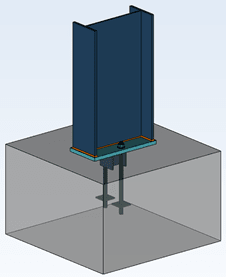
One thing that I've often been curious about is the buckling behaviour of a nominally pinned column under compression with a typical 'pinned' base plate.

Examples:
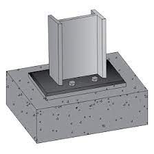
temp_lpzvch.jpg
temp2_zsevhq.png


For both of these I would consider these as 'pinned' connection and model them as such. Thus I'd would get zero moment transfer and effectively length of 1 if top of the column is braced but with no rotational restraint. As I understand it this is a pretty typical analysis approach under most codes and in most jurisdictions.

My question is:

Is this overly conservative? Would the compression and flat base plate not provide a degree of fixity and thus improve the critical buckling load? Here I define here a baseplate that is resting on a foundation but not restrained from uplift as a SEPPERABLE BASE PLATE.


It would surprise me if there isn't already plenty of literature on this matter. But I've never seen it. So I'd though I'd test it. And since I don't have a test laboratory at hand I figure I'd use FEA.

TEST APPROACH
-Non-linear plastic FEA analysis using NASTRAN
-Tri linear model of stress-strain curve used
-Iterative approach to converge on buckling solution (NASTRAN does have non-linear buckling analysis but not nonlinear PLASTIC buckling analysis)
-An additional lateral load of 1% of axial load was added to trigger the buckling. (This value is arbitrary but considered reasonable and conclusions not sensitive to this.)

TEST DETAILS
-Steel section: HEB160 S275 (EUROPEAN STEEL)
-Section length: 6600mm
-Minor axis translationally fixed, translationally fixed at the top, rotationally free.
-Base plate modelled in 3 ways; perfectly pinned; able separate but not slide AND; rigidly connected to foundation.
-Nominal mesh size - 50mm

CODE BUCKLING LIMIT:
Ncx = ~780kN (without any capacity reduction factor, both codes AS4100 and Eurocode within 2%)

FEA RESULTS
PINNED: Ncx = ~800kN
BASE PLATE (with sepparation): Ncx =~1150kN (equivalent le = 0.83)
BASE PLATE (RIGID): Ncx =~1150kN (equivalent le = 0.83)

As can be seen no discernible difference (<1% tolerance) between the rigidly connected base plate and a base plate with no uplift restraint.

CONCLUSION
In some/many circumstances it is not unreasonable to consider a typical column and base plate arrangement as 'fixed' for consideration of its buckling effective length. Without doing exhausting further testing I would suggest that this is reasonably representative for columns of 'intermediate slenderness' where inelastic buckling dominates.


ADDITIONAL TESTING
I was a little perturbed by the lack of discernible difference between a rigidly fixed base plate and one that is able to separate from its support. I hypothesised that this was due to inelastic buckling dominating before any appreciable rotation could occur at the base. This was tested by doubling the length of the HEB160 to 13200mm. To summarise this additional testing:
PINNED BASE = 275kN (Unreduced capacity in code 250kN)
BASE PLATE ON SURFACE = 460kN (equivalent le = 0.77)
FIXED BASE PLATE = 500kN (equivalent le = 0.74)

It was satisfying to see that for more slender columns the back calculated effective length approached the theoretical Euler elastic theoretical length. It was also satisfying to confirm that a fully fixed base base does exhibit better performance (as expected) compared to a separable base plate.


And here is a pretty FEA picture to keep everybody happy:
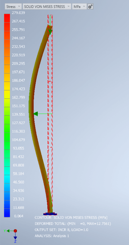
temp3_mzr32q.png
 
Replies continue below

Recommended for you

Human909, does the structure you're reviewing have done kind of knife edge loading?

Centondollar, what order of magnitude is the eccentricity you're worried about? What's stopping you from using the code value in the worst direction?
 
Human909 said:
For buckling all we need is a connection that is rigid enough to ensure that the half sine buckled shape is of a higher energy state than the quarter sine buckled shape.

This is the essence of it. It’s no different to a gravity wall. If rotation costs you energy then it won’t rotate. No anchor bolts needed.
 
Tomfh said:
This is the essence of it. It’s no different to a gravity wall. If rotation costs you energy then it won’t rotate. No anchor bolts needed.
Exactly. If the relevant failure mode doesn't involve rotation at the base, or has extremely minimal rotation at the base then the column capacity at ultimate limit state is pretty much equal a column with a rigid connection. As seen above the shape of the column at failure is pretty much equal to the pinned-fixed shape.

Which really shouldn't be a huge surprise because we shouldn't expect much influence from the bolts if they aren't being engaged!

Steveh49 said:
Human909, does the structure you're reviewing have done kind of knife edge loading?
100mm wide bearing plate completely central to column. With another column above transferring the axial loads again central. Geometry would imply <20mm eccentricity.
(Though I'll likely insist on a HEB180 instead of a HEB160, I like to sleep comfortably a night.)
 
Just saw human's latest analysis. I'm taking the load eccentricity to be 100mm off the flange, so 180 off centroid. That translates to 90mm approx at the base for rigid assumption, plus any non-linear amplification. Could you please extract base moment at buckling point for the fixed base case and the situation being discussed? It still seems to me that the relationship between the moment that the clamping can develop and what full rigidity demands is what determines where the answer sits on the Euler spectrum.

BTW, my objection to Euler is because it can't handle the variable base rigidity. Or, at least, doubtful anyone has bothered to modify the Euler analysis for this situation. I'm not objecting to its lack of physical imperfections (any more than usual - I think Euler's prominence in teaching actually makes it harder to learn stability design).

It's interesting that it achieves almost theoretical fixity of 0.7, vs 0.85 in code. I think the 0.85 limitation accounts for several of centondollar's concerns with the analysis, ie nothing that isn't dealt with routinely, if somewhat imprecisely. I'm happy to accept that because I know that even rigorous analyses won't match reality, so complicating the analysis further isn't warranted IMO. If the analysis came to 0.85 though, I would increase that to 0.9ish for design purposes.
 
steveh49 said:
Just saw human's latest analysis. I'm taking the load eccentricity to be 100mm off the flange, so 180 off centroid.
To be clear I used 100mm off centroid. (So 20mm off flange)

Moment at the base for non fixed 590kN, 100mm eccentricity: 60kNm for both. To be more precise:
5.96927e+7Nmm FIXED
5.96939e+7Nmm SEPERABLE

So effectively no difference. I did run this a couple of times to be sure. There is slightly more for non fixed that at first seems impossible but given you now have a changing contact patch it is within the realm of believability.


This is infact a fair bit larger than my structural analysis moment. I'm still scratching my head on this one.

In my structural analysis software I get 0.1m x 590kN - 15kN x 6.6m = 40kN which makes sense from a free body diagram perspective. The 15kN is the reaction from the translationally restrained top.

In FEA I get identical reactions and have identical eccentricities but I get 60kNm instead. Which is the inverse. I'm done with this for the moment...

Displacement and shape between the two analysis programs are near identical so they are modelling the behaviour the same, just presenting the output values in a different manner.
 
human909 said:
To be clear I used 100mm off centroid. (So 20mm off flange)

Moment at the base for non fixed 590kN, 100mm eccentricity: 60kNm for both. To be more precise:
5.96927e+7Nmm FIXED
5.96939e+7Nmm SEPERABLE

So effectively no difference. I did run this a couple of times to be sure. There is slightly more for non fixed that at first seems impossible but given you now have a changing contact patch it is within the realm of believability.

Not what I'd have expected given the visible separation in your output image from the earlier post. Nor when the base plate is only 200mm wide, so the centroid of reaction is outside the base plate.

human909 said:
In my structural analysis software I get 0.1m x 590kN - 15kN x 6.6m = 40kN

Is that elastic analysis software with no initial bow shape? That's about what I get by hand: 29.5 kNm linear * 1.36 amplification. (And also from software analysis to check, assuming rigid connection at base for simplicity.)

With a 12mm sine initial shape, it goes up to 47 kNm at the base which is about the limit for no-bolts base moment I estimate could be sustained. So close-ish to fixed but, by this stage of analysis which is needed to confirm the base fixity, the effective length is almost irrelevant.

EDIT: Where does it fail in the non-linear analysis - is it just section capacity at the top? Maybe similarity to code capacity is just a coincidence because of the small eccentricity modelled.
 
Yeah I was quite surprised to see the identical moments. But it think I makes sense... The clamping force from axial is load very dominant. The energy required to get rotation occuring at the base is high.

And sure the image I had shows sepparation. But that is only 0.15mm and that is very close to the limit. Much more and you have buckling failure.
 
@human909,

I realize that I am late into the discussion but I find what you have done interesting. But I have a few questions, most of them actually based on your description in the first post. I am just curious regarding you approach to the problem [smile]. And I have not read every post and reply in detail so I may have missed something.

1. You are using Nastran, what specific Nastran "flavour" are you using? Autodesk/Inventor, MSC, NX or someting else.
2. You have modelled a steel section HEB160, that means basically plates with size 160 mm and thickness 13 and 8 mm. You mention a nominal mesh size of 50 mm but why have you used solid elements? I would use plate elements for a number of reasons.
3. At the base of the column, is there anything that could support tension? I assume that it is just two surfaces in "simple contact". That means that the lateral load you use to trigger the buckling must be supported by something, possibly friction?

First regarding the question of if the base is pinned or fixed. I think it is a question regarding the ratio between moment at the base and axial load, and of course size/stiffness of the base plate. Compare it to the foundation for a chimney. If the foundation is big enough it can support the moment, if not, you may have a problem. But that does not mean that I would design a baseplate for a steel column without any bolts [smile].

What surprises me in your analysis is the results regarding capacity. If I understand it correct you get the same results as for Euler buckling and they are the same as the results from AISC or Eurocode. From the Nastran analysis you should be able to get similair results as for Euler buckling. It is not stricktly speaking Euler buckling when you use non-linear FEA, it depends on what non-linearity is actually happening. I would say that it may be linear buckling even if you use a non-linear analysis.

But that fact that you get the same results as the code for capacity surprises me a bit. You mention Eurocode as a reference. Have you checked EN 1993-1-5 Plated structural elements, Appendix C? There you have an approach to using FEM for structural analysis. I assume that you have used a non-linear material model and large displacement analysis. But based on your results your "arbitrary" 1 % lateral load is able to replace the imperfections that also need to be included in the analysis.
If I instead look at the reults from gusmurr (3 Nov 22 00:37) they also include the imperfections. So that analysis seems more in compliance with Eurocode's approach.

I suspect that the accuracy in the 1 % lateral load is more or less "pure luck [smile]" but I don't know. But since I often work with non-linear analysis's I found the thread interresting.

Edit: I noticed someting in a later post in the thread regarding imperfections. I think l/200 may be a bit conservative, l/300 may be more appropriate for an HEB section with plastic analysis (EN 1993-1-1, Table 5.1). The imperfection is also used to include initial stresses. l/1000 is manufacturing tolerance only (EN 1090-2).

Thank you
Thomas
 
Hi ThomasH. I'll try to answer as much as possible. Though I am busy at the moment so my responses will be brief.

ThomasH said:
1. You are using Nastran, what specific Nastran "flavour" are you using? Autodesk/Inventor, MSC, NX or someting else.
2. You have modelled a steel section HEB160, that means basically plates with size 160 mm and thickness 13 and 8 mm. You mention a nominal mesh size of 50 mm but why have you used solid elements? I would use plate elements for a number of reasons.
3. At the base of the column, is there anything that could support tension? I assume that it is just two surfaces in "simple contact". That means that the lateral load you use to trigger the buckling must be supported by something, possibly friction?
I'm using Nastran Incad Autodesk Inventor. Solid elements because that is what I'm used to. I usually use shell elements for thin walled sheet vessels. I won't make claims that my approach is the ideal FEA approach.

ThomasH said:
But that does not mean that I would design a baseplate for a steel column without any bolts smile.
I would never want to do that.

ThomasH said:
What surprises me in your analysis is the results regarding capacity. If I understand it correct you get the same results as for Euler buckling and they are the same as the results from AISC or Eurocode.
No. I am not using Euler buckling. And in the case of my second set of results which match up closely back calculated the effective length from the code. The code used is AS4100 though I did check it against eurocode with similar values.

ThomasH said:
I would say that it may be linear buckling even if you use a non-linear analysis.
It is definitely non linear plastic analysis. As said I'm not even using the buckling analysis function on Nastran. I'm iterating to the point just prior to failure.
 
steveh49 said:
Centondollar, what order of magnitude is the eccentricity you're worried about? What's stopping you from using the code value in the worst direction?
I explained the mechanics of the problem (if it is to be treated as a "footing" problem or a "post-tensioning" type problem), and in that explanation I hope I made it clear that it is not the order of magnitude or direction that is the issue. The issue is in the mechanics, not in code values (which are not necessarily realistic or generalizable, to the detriment of all who are required to cite code) for eccentricity.

Again, how do you propose that the precompression from eccentricity (P*e/W) is to be controlled such that it follows the change of direction of lateral load? This is a requirement for the precompression (and fixity without resorting to bolting) to be guaranteed.
 
human 909,
What is the axial load you've used in the analysis? If you pin the top and allow geometric non-linearity, the column will stiffen itself due to restricted membrane deformation (pin prevents stretching), which does not necessarily reflect a real case.

What happens if you run the same analysis for a rigid-free (cantilever) column?

PS. 60kNm moment is practically nothing. Can you replicate this calculation with a much larger column and much larger horizontal force (say, 2-5% of axial load) or a distributed lateral load (from e.g. wind) with a large tributary area?
 
Hi human909,

Thank you for you reply, brief but still clarifying [smile].

human909 said:
I'm using Nastran Incad Autodesk Inventor. Solid elements because that is what I'm used to. I usually use shell elements for thin walled sheet vessels. I won't make claims that my approach is the ideal FEA approach.

That means that you use what used to be called NEi.Nastran and then it became Autodesk Nastran. I used that software for some years before Autodesk bought it. At the time a good solver, today I have no informed opinion. Like I said, for me this is a plate model. There are a number of reasons for that but I skip that for now.

human909 said:
No. I am not using Euler buckling. And in the case of my second set of results which match up closely back calculated the effective length from the code. The code used is AS4100 though I did check it against eurocode with similar values.

Ok, I read Euler buckling somewhere but there were a lot of posts so I have probably misunderstood. It certainly make the results more resonable. Still, I assume that imperfections would influence the results.

human909 said:
It is definitely non linear plastic analysis. As said I'm not even using the buckling analysis function on Nastran. I'm iterating to the point just prior to failure.

What I meant was that it may be linear to some extent even if you use a non-linear analysis. First you have the large deformations that means that the solver updates the geometry with deformations as the load increases. Second you have the "plastic" part but that also implies that your stress level is beyond yield, otherwise the material will have linear behaviour. In your first post you mention S275 steel and the figure shows 279 MPa. Depending on exactly how that number is computed it may mean yielding but it doesn't have to mean that. If I compare to the stresses from 1 Nov 22 18:43 they are significantly higher, yielding or something else? So even if you have plastic as an option, it does not mean that the material actuelly goes beyond yield.

If I instead compare to the results from gusmurr 3 Nov 22 00:37, they show a clear plastic zone that I have not seen in your analysis's. In that analysis the failure is obvious, and that analysis includes imperfection close to the recommendations in the Eurocode.

Note, I am not trying to criticize the analysis. But there are things that I think could be improved. If that would lead to a different result of just conform the current conclusion, that is another question [smile].

Thank you
Thomas
 
ThomasH said:
Note, I am not trying to criticize the analysis. But there are things that I think could be improved.
I agree things can be improved and generally I agree with most of your suggestion of areas of improvement.

ThomasH said:
So even if you have plastic as an option, it does not mean that the material actually goes beyond yield.
The material is definitely yielding in the analysis. Turn it off you get higher stresses, lower strains and lower deflection. Not to mention significantly higher buckling capacity

As far as further work on this goes, I'd like tidy things up a bit to tighten up. Particularly by using higher initial eccentricity AND initial imperfection as you mention. However I'll unlikely have the time in the next few weeks.

Overall implementing such items will reduce the capacity but I believe that the base plate will largely remain behaving as 'fixed' as far as buckling behaviour goes. So I'd expect the ultimate conclusion remains unchanged where axial loads are grossly dominant.

Of course there would be a tipping point. As moment relative to axial load increase the buckling behaviour will change, very likely in a non linear bifurcation manner. This would be an interesting point to find. Though for my purposes here I am considering a situation where axial load is very much the dominant load.


And of course the final question is; To what end is having this knowledge? I'm not about to start designing new structures using a smaller effective length and lighter columns. That said, it might come in handy on the occasion when I do choose to approve an existing structure or modification that is a little closer to the edge of conservatism.

Personally I like seeing my structures having a CAPACITY/ULS = 1.3-1.5. I've spoken to other engineers who are happy with >1.01. This is the sort of knowledge that I'd intend to employ only if I awkwardly find myself with a CAPACITY/ULS = 0.95 and I can suitably justify a smaller effective length to get me over the line. This isn't a situation I'd want to put myself in though.


As far as the original OEM supply goes that initiated my asking myself this question. Lets just say that HEB160 won't be being used.
 
Centondollar, I think I follow your argument now but still disagree. Rotation of the column base is not 'free' as in an ideal pin. It is accompanied by a bending moment in this case, up to some point. I think it's fair to say there was an implicit limitation of this discussion to columns with minimal external moment at the base, so the bending moment that can develop is available to resist non-linear effects related to axial compression. The moment will develop in the necessary direction without external interference.
 
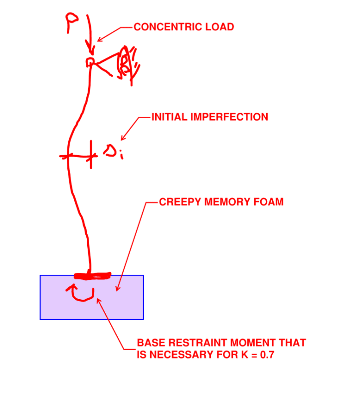
Fascinating discussion. I myself have availed myself of base connection stiffness on a few renovation assignments (for buckling restraint). There is, however, one thing that's always nagged at me when doing this: creep. The grout bed, the concrete, the soil, and the bond on any active tension anchors will tend to creep over time, even at low stress levels. Such creep would tend to dissipate the base restraint moments that one is hoping to mobilize for a K=0.7=ish column design. The impact of this would be affected by the rate of loading of course. As such, I get less comfortable with this as dead load becomes a larger portion of the total load.
 
KootK said:
Fascinating discussion.
[love2] Aww... Thanks KootK. I was wondering when my favourite sparring partner from the fly brace thread would show up! [upsidedown]

KootK said:
I myself have availed myself of base connection stiffness on a few renovation assignments (for buckling restraint)
Good to know there are other engineers out there taking advantage of the base connection stiffness out there. Some of the respondents here seemed to have reacted to me like I have three heads by even suggesting the possibility.

KootK said:
creep. The grout bed, the concrete, the soil, and the bond on any active tension anchors will tend to creep over time, even at low stress levels. Such creep would tend to dissipate the base restraint moments that one is hoping to mobilize for a K=0.7=ish column design. The impact of this would be affected by the rate of loading of course. As such, I get less comfortable with this as dead load becomes a larger portion of the total load.
An interesting factor. And something to think about if you are choosing to walk the line of unconservatism. But is it really that influential? You'd need some pretty eccentric loads to cause creep. And the same creep would be appearing on regular pinned base plates that we have all over the place in our structural steel buildings. If creep was a factor we'd be seeing our buildings all the time.

(Not disagreeing with you here, just being contrarian.) [thumbsup]
 
human909 said:
But is it really that influential?

I don't know, and that's the problem.

human909 said:
You'd need some pretty eccentric loads to cause creep.

I disagree. Consider:

1) Creep in concrete occurs at even very low levels and;

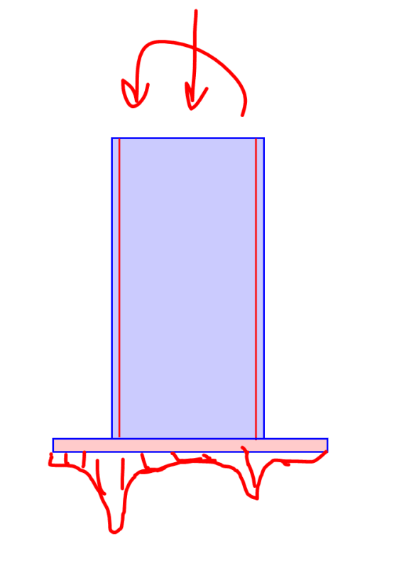
2) The base moment that concerns me requires no eccentricity of load at all. Rather, it would be based on the real world / moment amplification model of buckling (as opposed to bifurcation) wherein the column possesses imperfections that just grow over time. See the sketch below, imagining the concrete to be something like the memory foam that they make those sweaty mattresses out of. I see all real world base conditions as less creepy version of this. In this case, I feel that:

a) K = 0.7 would be reasonable for instantaneous loads but;
b) K = 1.0 would be appropriate for slowly applied loads as the base rotational restraint would tend to diminish with creep.

human909 said:
If creep was a factor we'd be seeing our buildings all the time.

I don't think that's true because:

3) The overwhelming majority of columns are designed K=1.0 and, so, do not depend on the presence of base rotational restraint.

4) Where you get serious, deliberate base moments, as with some moment frames, the peak load cases are usually transient and short lived and, thus, not punishing from a creep perspective.

c01_jukkjd.png
 
10 MPa sustained stress gradient / 35,000 MPa modulus * (1 + 2.5 creep) = 0.001 strain gradient due to sustained load.

10 MPa / 35,000 = 0.0003 strain gradient due to short-term load.

Total strain gradient = 0.00013.

25 mm grout.

Estimate 100mm/2 effective compression depth in footing before the load spreads out.

0.1 mm differential displacement / 160 mm section depth = 1/1600 slope. That's not stopping me assuming I've already gone to the dark side of K<1.
 
But then there's the soil. And flexure in the footing. And the fact that, as shown below, the strain under most column base plates will be highly localized and nothing like a uniform gradient.

c01_qv1xic.png
 
The soil and footing are common to the case of a conventional rigid connection. If we can't rely on them then the discussion is over AFAIC. I think they're part of the reason we use K = 0.7 or 0.85 instead of 0.5 and 0.7.

Creep will even out the stress in the grout. We get the good with the bad.
 
Status
Not open for further replies.

Part and Inventory Search

Sponsor