Continue to Site

Eng-Tips is the largest engineering community on the Internet

Intelligent Work Forums for Engineering Professionals

  • Congratulations KootK on being selected by the Eng-Tips community for having the most helpful posts in the forums last week. Way to Go!

Building geometry concern 11

Status
Not open for further replies.

hoshang

Civil/Environmental
Jul 18, 2012
479
Hi all,
please find the attached thread:
javascript:eek:penindex(450,450,'
BAretired said:
There are no beams on gridlines D and E other than walls, acting as deep beams and shear walls combined.
BAretired said:
The black object is hanging from the cantilevered wall above, which means that forms must be kept in place until the wall above cures.
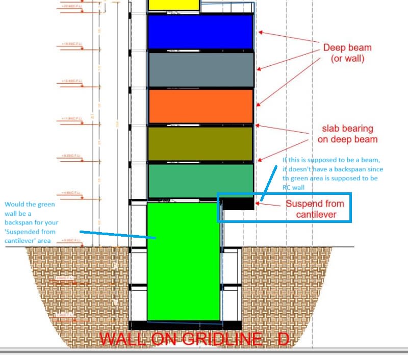
Capture_sfzhfx_pupbtf_l9hzke.jpg

So the black object is hanging from the cantilevered wall above, does this mean the cantilevered wall above (the dark green one) is acting as a hanger for the cantilever slab below (the cantilever slab at level +4.60) at the same time it acts as bearing wall supporting the cantilever slab resting on it (the cantilever slab at level +8.20)? If so, how it can be modeled in an FEA software?
 
Replies continue below

Recommended for you

On a more serious note, I'd like to commend BAretired for his effort and time! Such great effort to help on the forum. I wish I could give you a medal of honour.

Let me buy you a drink sometime...
 
hoshang said:
I hope Celt83 who have experience with the software I'm using could comment on this.

What you really need is someone with experience in structural engineering and hand this project off to them entirely, before you end up with three adjacent buildings tipping over into your excavation.
 
You can do whatever you want in the software but reducing the axial stiffness of a concrete column does not align with reality. Robot expects you as the user to have sound fundamental knowledge in engineering.
 
Hi all,
My thought is using response spectrum analysis rather than ELF code provisions for such a geometry.
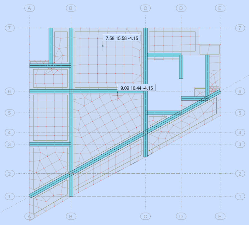
The center of gravity and center of rigidity are as in the image below
Screenshot_2024-06-13_233557_pgtd6a.png

What one can do to make these centers coincide? My thought is enlarging columns and walls.
 
To my uninformed eye, the CG, in the middle of the plan at (9.09, 10.44), looks about right;
but the center of rigidity, close to the top edge at (7.58, 15.58), looks very "funny".

"Hoffen wir mal, dass alles gut geht !"
General Paulus, Nov 1942, outside Stalingrad after the launch of Operation Uranus.
 
rb1957 said:
To my uninformed eye, the CG, in the middle of the plan at (9.09, 10.44), looks about right;
but the center of rigidity, close to the top edge at (7.58, 15.58), looks very "funny".
What building configuration would you recommend for columns and walls so the center of rigidity would be close to center of gravity?
 
none, not a clue. I was just observing that the data (the center of rigidity) looked out of place.

"Hoffen wir mal, dass alles gut geht !"
General Paulus, Nov 1942, outside Stalingrad after the launch of Operation Uranus.
 
hoshang said:
What building configuration would you recommend for columns and walls so the center of rigidity would be close to center of gravity mass?

A perfectly symmetrical one.
 
Status
Not open for further replies.

Part and Inventory Search

Sponsor