Continue to Site

Eng-Tips is the largest engineering community on the Internet

Intelligent Work Forums for Engineering Professionals

  • Congratulations KootK on being selected by the Eng-Tips community for having the most helpful posts in the forums last week. Way to Go!

Building geometry 10

Status
Not open for further replies.
Replies continue below

Recommended for you

Hi BAretired,
Another query.
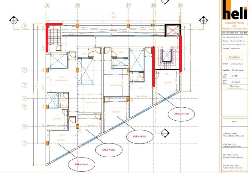
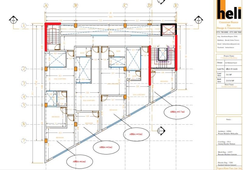
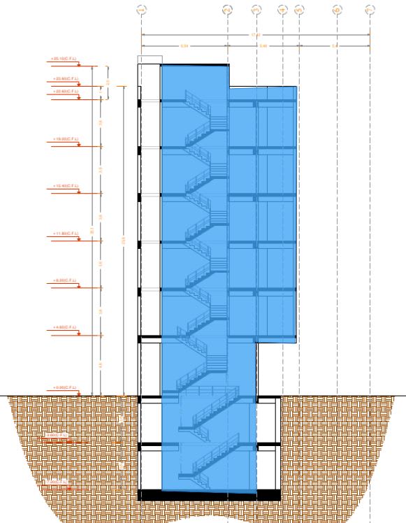
The right side two proposed walls support a cantilever slab in the front of about 2.85m span (see the image)
Capture_wlvinj_x9ibow_owhkhf.jpg

How one should count for this?
Maybe one of the thoughts would be (RC wall) hangers from floors above.
 
@hoshang,

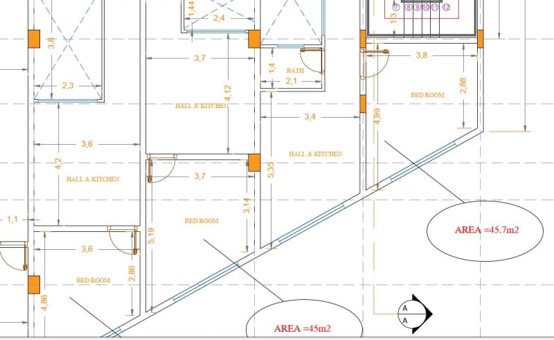
The Architectural drawings show a cantilever of approximately 2.85m, but in no case does the slab cantilever that far. Section A-A shows beams extending out to the end of the cantilever. The Architectural plan indicates walls spaced less than 4m apart. It is assumed that the beams are aligned with the walls, so there is no instance where the slab is having to cantilever 2.85m.

If you are performing the structural design, you need to start with some framing plans for each floor. I have seen none to date. I see no need for any hangers from floors above. But it might be a good idea to add a beam at the window wall (parallel to Main Street).

Capture_e0waqy.jpg
 
BAretired said:
It is assumed that the beams are aligned with the walls, so there is no instance where the slab is having to cantilever 2.85m.
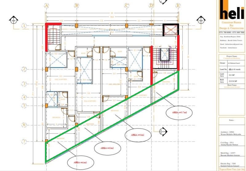
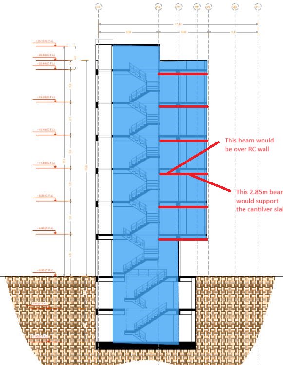
If you remember, we went through the discussion till proposing concrete walls (red lines) rather than columns for the building framing at these locations. Please find the attached image. As you can note, there would be a cantilever slab spanning 2.85m (green line) that need to be supported. Can beams extend over the right side proposed walls?
Capture_wlvinj_x9ibow_owhkhf_y0e7f9.jpg

My thought is using (RC wall) hangers from floors above rather than beams extending over the proposed RC walls (red lines in the attached image) supporting the cantilever slab. Your response would be highly appreciated.
 
hoshang said:
Can beams extend over the right side proposed walls?

Well, why not? Beams can extend over or be cast monolithically with the walls. Beam depth is not even limited by headroom on Grid Lines D and E. You can extend the entire wall if you wish. To cantilever the slab inside the green lines without rigid beams would be a mistake in my view because of excessive deflections at the exterior window wall.

There will be issues arising when you draw the structural framing plans, but until you prepare them, some issues will almost certainly be missed.
 
BAretired said:
If you are performing the structural design, you need to start with some framing plans for each floor. I have seen none to date.
This will be the framing plan for the whole eight floors:
Capture_wlvinj_x9ibow_owhkhf_rf8ylv.jpg

BAretired said:
Well, why not? Beams can extend over or be cast monolithically with the walls.
Do you have a detail (or even a hand sketch) for a beam extending over or cast monolithically with the wall?
My worry would be:
1- How wide would be the beam (as wide as the wall or wider than the wall)
2- If the former, how one provide stirrups for the beam (is it needed at all? Since I think no shear will be induced in the beam. The same with longitudinal reinforcement since no bending moment will be induced in the beam, i.e., the whole length of the beam is supported by the wall).
3- My thought would be that one would provide longitudinal reinforcement in the beam over the wall only to be a back span of the beam supporting the cantilever slab. Am I correct?
Your response would be highly appreciated.
 
Do you have a detail (or even a hand sketch) for a beam extending over or cast monolithically with the wall? No! See below.
My worry would be:
1- How wide would be the beam (as wide as the wall or wider than the wall)
Wider would be structurally preferable, but projections are not acceptable, so extend the wall to the end of the cantilever on Grids D and E from First Floor to Roof. Below First Floor, Column D3 needs to be increased in width.
2- If the former, how one provide stirrups for the beam (is it needed at all? Of course it is! Since I think no shear will be induced in the beam. Wrong! The same with longitudinal reinforcement since no bending moment will be induced in the beam, (wrong again) i.e., the whole length of the beam is supported by the wall).
3- My thought would be that one would provide longitudinal reinforcement in the beam over the wall only to be a back span of the beam supporting the cantilever slab. Am I correct? No, you are not. A backspan has both shear and moment for its full length.
 
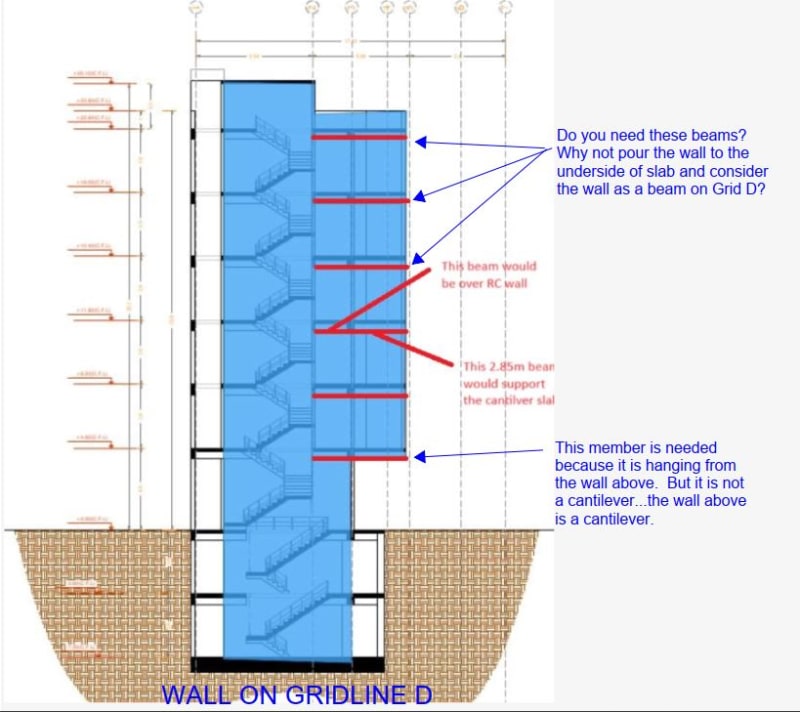
Instead of widening Column D3, the wall on Line D could be extended as shown in blue below:

Capture_genjuq.jpg
 
BAretired said:
no shear will be induced in the beam. Wrong! The same with longitudinal reinforcement since no bending moment will be induced in the beam, (wrong again) i.e., the whole length of the beam is supported by the wall).
Per your response, a beam over RC wall would be assumed as beam-on-elastic-grade, is it?
BAretired said:
Instead of widening Column D3, the wall on Line D could be extended as shown in blue below:
Per your image, the RC walls above a cantilever slab would be hangers for cantilever slabs beneath the RC walls, are they? Keep in mind my considerations are as follow:
Capture_genjuq_u4tef0.jpg
 
Hi BAretired,
Can you elaborate more on your last post? I can't catch your point.
 
"Do you need these beams?" is a question to you. I do not think you need them on Grid D. If you believe that they are acting like cantilevers supporting the slab at each floor, I would point out that the back span is too short. The back span for a cantilever should be at least as long as the cantilever. On Grid D, the wall is to be extended to the North, so the wall itself is the cantilever. That is also true for Grid E.

You have not provided structural framing plans, but I am concerned that the 2.85m cantilever will require a different solution than that shown on the architectural drawings. I am wondering if you intend to provide a transfer structure at First Floor in order to enable a more economical solution for the Typical Floors and Roof. It would seem to make sense to me.


hoshang,

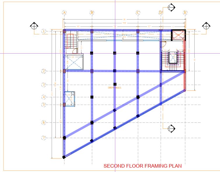
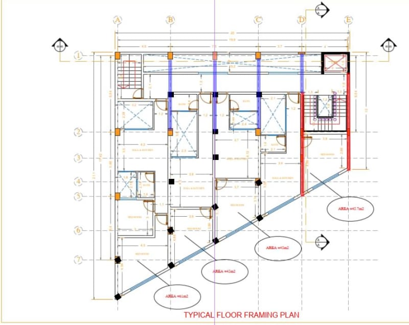
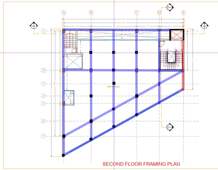
Further to my earlier post, I attach a proposed Second Floor Framing Plan and Typical Floor Framing Plan for your consideration.

The Second Floor is a Transfer structure. The beams are shown in blue. Wall support is in red. The black squares are columns extending from top of Second Floor to Roof.

The Typical Floor is a flat plate with beams only where required to provide lateral support to the wall on Gridline 1. This permits residential floor headroom to be reduced substantially, resulting in shorter walls, fewer risers in the stairwells and ease in using fly forms.

Capture_m7lmsa.jpg


Capture01_jwvfiv.jpg
 
lexpatrie said:
The longevity of this thread blows my mind.

Yes, it is getting much too long. And there are still issues which have not been resolved.
 
your work in helping Hoshang is astonishing !

"Hoffen wir mal, dass alles gut geht !"
General Paulus, Nov 1942, outside Stalingrad after the launch of Operation Uranus.
 
The patience and guidance offered by BAretired is admirable.
 
Thanks rb1957 and Eng10680, but the patience is running low.
 
yeah, I gave up long ago, and have kept a watching brief on this.

Funnily enough, I had some experience with underground garages on my recent trip, and even quite spacious layouts can require "16" point turns.

The layouts are, IMHO, completely unrealistic and the OP seems to be ignoring the (rotting and festering carcass of an) elephant in the room.

"Hoffen wir mal, dass alles gut geht !"
General Paulus, Nov 1942, outside Stalingrad after the launch of Operation Uranus.
 
BAretired said:
The Second Floor is a Transfer structure.
Do you intend to provide a Transfer slab for the Second Floor?
Capture_m7lmsa_u8afxa.jpg

If so, should the Transfer slab be of uniform thickness throughout the First floor area? How much thick this Transfer slab should be to accommodate the planting of the new proposed columns? Do you have a detail for such planting of new columns in a Transfer slab?
Can the skewed columns be made of regular columns (rather than skewed)? Or circular columns?
 
hoshang 23 Mar 24 09:27 said:
This will be the framing plan for the whole eight floors:

Structurally, this is possible, but providing a 2.85m cantilever at each typical floor and roof is uneconomical. A transfer structure at a lower level would be better. Then the typical floors and roof could be a simple flat plate.


Status
Not open for further replies.

Part and Inventory Search

Sponsor