I've looked through some posts on this, the most relevant conversation is here:
We currently use the bullet-nose pins on page 12 of this Carr Lane catalog:
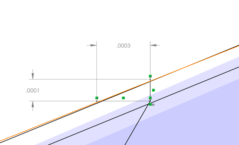
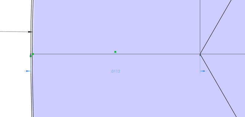
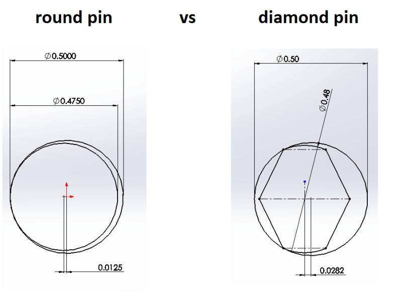
Specifically, I am working with the 1/4 inch nominal diameter. Almost every source I can find claims the diamond pin functions the same as a pin and a slot. I've drawn this up multiple times and it just doesn't seem to work. When the diamond pin moves relative to it's mating bushing, the arc of the diamond pin intersects the bushing ID long before the "diamond" edges do anything. There is a VERY slight difference, .0003 radial movement for the diamond pin vs .0001 for the round pin).
I am looking at these pins from an MMC perspective and math is showing that I would need to specify an RFS positional callout of .0008. Even at LMC we are still looking at a requirement of around .0015. This is treating one hole as the datum.
I do understand that diamond pins help with perpendicularity, basically taking that out of the equation by allowing slight rocking. I do not see how a diamond pin helps when we look at a 2D plane. It does not seem to function like a pin in a slot like so many resources claim.
We already have molds using the 1 round, 1 diamond pin setup but our techs are having to slam them together with hammers and pry them apart with crowbars. I can see where the pins and bushings have been chipped and cracked. We have a mold made by an external supplier using the same pieces, their mold goes together smoothly. Are they just hitting that .0008 tolerance? Or am I missing something?
Please help me understand!


