Eng-Tips is the largest engineering community on the Internet

Intelligent Work Forums for Engineering Professionals

  • Congratulations waross on being selected by the Tek-Tips community for having the most helpful posts in the forums last week. Way to Go!

Can anyone explain how diamond locating pins work like a pin and slot? 1

Status
Not open for further replies.

Jste

Mechanical
Mar 31, 2021
17
0
0
US
I've looked through some posts on this, the most relevant conversation is here:
We currently use the bullet-nose pins on page 12 of this Carr Lane catalog:
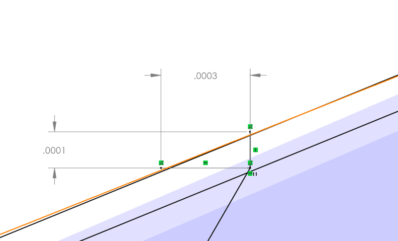
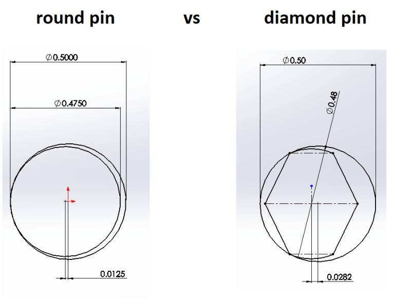
Specifically, I am working with the 1/4 inch nominal diameter. Almost every source I can find claims the diamond pin functions the same as a pin and a slot. I've drawn this up multiple times and it just doesn't seem to work. When the diamond pin moves relative to it's mating bushing, the arc of the diamond pin intersects the bushing ID long before the "diamond" edges do anything. There is a VERY slight difference, .0003 radial movement for the diamond pin vs .0001 for the round pin).

I am looking at these pins from an MMC perspective and math is showing that I would need to specify an RFS positional callout of .0008. Even at LMC we are still looking at a requirement of around .0015. This is treating one hole as the datum.

I do understand that diamond pins help with perpendicularity, basically taking that out of the equation by allowing slight rocking. I do not see how a diamond pin helps when we look at a 2D plane. It does not seem to function like a pin in a slot like so many resources claim.

We already have molds using the 1 round, 1 diamond pin setup but our techs are having to slam them together with hammers and pry them apart with crowbars. I can see where the pins and bushings have been chipped and cracked. We have a mold made by an external supplier using the same pieces, their mold goes together smoothly. Are they just hitting that .0008 tolerance? Or am I missing something?

Please help me understand!
 
Replies continue below

Recommended for you

Jste,

A diamond pin and hole isn't equivalent to a pin and slot, its just another solution - you could consider it an approximation of a pin/slot. Two precise holes where one has a diamond pushed in is just easier to make in most cases than a precise slot. The slot will be more forgiving during assembly though for the reasons you noted, as the point on a diamond pin can interfere with the arc of the mating hole with location/orientation error in the direction towards/away from the axis of the [x,y] locating round pin. A round pin in a slot on the other hand has total freedom in this direction. In this way the diamond pin can be somewhat of a compromise, but if held accurately can be a workable compromise.

From my experience issues with pins often comes down to a combination of orientation/location error/deviation and often mainly driven by orientation, not just pure location. Perhaps specifying a tighter orientation tolerance/refinement might help. Using shorter pins might alleviate this as well. Also check the fit, if the interference fit is too heavy you may induce orientation error of the actual pin where the hole itself was more accurate.
 
Jste,

You have a plate with a flat bottom and two clearance holes for dowel pins. You call up flat bottom as your datum feature[ ]A controlling[ ]Z and rotation about the X and Y[ ]axes. One of your holes is datum feature[ ]B controlling movement in X and[ ]Y. Your second hole is datum feature[ ]C controlling rotation.

We now have a practical problem with the tolerances locating your holes and pins. The diameter of your holes exceeds your pins by the clearance[ ]C. The tolerance between the two holes must be [±]C or tighter to ensure the thing can be assembled. If your holes clear screws, this works. If you have dowel pins with very accurate fits, it does not work. It is extremely difficult to position dowel pins and reamed holes accurately enough to assure assembly. Your solutions are...

[ol]
[li]Drill and ream the holes and insert the pins after assembly. You achieve repeatability, not accuracy.[/li]
[li]Make the datum[ ]C hole a slot, making the centre to centre distance not critical.[/li]
[li]Make the datum[ ]C pin diamond shaped. This accomplishes the same thing as a slot.[/li]
[/ol]

--
JHG
 
Chez311,

I think you are referring to the same concept that was in the other thread I listed and that also shows up in various other sources. My confusion is that when I draw up the diamond pin and its mating bushing at MMC, the benefit from the diamond cut is miniscule! I attached some images to show that the "point" of the diamond will never contact the bushing ID moving on a 2D plane. It will help with perpendicularity misalignment, but a pin and slot are mainly used for precise planar location (I think)

drawoh,

Thanks for another response, I appreciate the thoughts you had to share in the previous thread. Your 1st and 2nd point I agree with. We can use a slotted bushing to achieve point 2, point 1 we might do so each of our molds is unique and not interchangeable. Depends on how our machinist feels about the setup.

However, your point 3 is where I disagree. As long as there is a chord that goes through the center of a circle, it is practically the same as a round pin for a 2D location. At least for tight clearance fits. As you get looser it becomes more like a slot.
Diamond Pin Geometry:
dpin_lo1mvw.png

Zoom into trimmed arc:
zoom_arc_bept8l.png

Zoom into diamond tip:
zoom_point_hhtrfm.png
 
Jste,

Diamond pins work. The pin on your sketch is too wide. The width of the pointy part is irrelevant. The diameter contact is short enough that there is clearance to the left and right, even though movement up and down is controlled.

--
JHG
 
What you have drawn up above is exactly why diamond pins are used... you're making your own argument.

The sharp corner of the diamond pin is not supposed to ever touch anything.

In your drawing above, the actual radial clearance from the pin to the bore is something less than .0001 (I'm too lazy to do the math). But, as you've stated, the clearance on the x axis (as oriented in your drawing) is .0003.

If the diamond pin were instead perfectly round, the clearance on the x-axis would be whatever the radial clearance is. So using a diamond pin there has resulted in a condition where the bore can be 'out of position' by a margin 300% higher and still fit over the pin.

This is exactly why diamond pins exist.
 
I think you are referring to the same concept that was in the other thread I listed and that also shows up in various other sources.

I read your other thread, this was a separate response to the questions and issues referred to specifically in this thread.

I also gave you specific advice in the second half of my response on the assembly you said you were having trouble with and possible root causes. Seems like you may have glossed over that.

the "point" of the diamond will never contact the bushing ID moving on a 2D plane.

Thats the whole "point" of the diamond pin (pun intended). The pin is relieved in the direction pointing towards the round pin to provide clearance, its never meant to contact that point its supposed to free most of the constraint in that direction. If your round and diamond pins are aligned along the x-axis, your round pin is meant to constrain translation [x,y] and the diamond pin is meant to help constrain translation [w] only. A second round pin would fight for constraint of [x,y] - hence why we often consider this "over-constrained". Obviously a diamond pin is not perfect in this regard, and orientation error along the x-axis (towards/away from the round pin) may cause issues - but less so than two round pins.

My confusion is that when I draw up the diamond pin and its mating bushing at MMC, the benefit from the diamond cut is miniscule!
The benefit of a diamond pin is actually quite noticeable. I've exaggerated the dimensions to show the difference more easily, but the relative differences are proportional regardless all else being equal. With a diamond pin having the same diameter but the sides relieved allows over twice the misalignment in the [x] direction while retaining accurate constraint of [w] rotation, aka clocking.

diamond_pin2_rn5ml7.png
 
Thanks for the replies all three,

I appreciate you be willing to restate your points, in retrospect posting the pictures first would have helped so I could be sure we were all talking about the same things. I think my confusion derives from the fact that 200% gain of .0001 is still only .0003, which doesn't help as much as I thought it would.

I'm having a hard time grasping that we are able to hit within .0006 to .0014 (I think, I cheated and drew it for these numbers). But I guess that averages out to about .001 which seems more reasonable if the pins and bores are not at worst case. I just feel very weird putting .0006 on my drawing.

Thanks for your help and patience! I wanted to make sure there wasn't something I was totally missing. I think it's more that I haven't designed molds or assemblies that needed precision on this level.
 
Another way to go about it is the diamond pin will allow axial misalignment equal to the .0003 distance you show in your second snapshot. A round pin of the same diameter (.2499) will only allow (.2501-.2499)/2 = .0001 misalignment. Thats 1/3 that of the diamond pin!*

This is misalignment of the axis, so in Y14.5 terms that a round pin requires a .0002 dia or better position tolerance to prevent interference. The diamond pin allows expanding this to .0006 dia or better.

We can even take this a step further and put together some equations. What you're probably concerned with is the minimum allowable misalignment at MMC.

Where D is the hole diameter and d is the pin diameter, and r is the perpendicular distance from the center of the pin the the chord of the diamond pin back cut region (ie: the chord between where the edge of the back cut ends on either side).

For a round pin:
(D[sub]MMC[/sub]-d[sub]MMC[/sub])/2

For a diamond pin:
sqrt((D[sub]MMC[/sub]/2)[sup]2[/sup]-r[sup]2[/sup])-sqrt((d[sub]MMC[/sub]/2)[sup]2[/sup]-r[sup]2[/sup])

*So my initial statement was I think correct but misleading because the relative chordal length changes when the ratio of the diameters changes - ie: difference between my .500/.475 and your example .5001/.4999

I think my confusion derives from the fact that 200% gain of .0001 is still only .0003, which doesn't help as much as I thought it would.

Thats a 3x increase! When we're talking about tenths (ten thousandths) we're already talking about tiny fractions of an inch, increases to .0003 are equally tiny, but huge relative increases. In the spirit of Einstein, its all relative.
 
Yes, it helps a lot more than I though it would! Our internal machinist is fine with me putting .0006, in his words "I've been making them for awhile and they go together". I can't really argue with that! But when it comes to sending parts like these out, I really didn't want to put something less than .001. I'm just not in tune with what is reasonable yet, I need a few more years in me. Wording it as a 3x increase makes it much more clear, it's those decimal places that got me so twisted up.
 
Jste,

Keep in mind that while your radial location can be opened up, your orientation requirement still must be tight. This would require orientation refinement to at least within .0002* similar to your round pin. You could I guess use bidirectional tolerances on this as your orientation can be opened up in the radial direction (towards the corresponding round pin) but I doubt this would be very helpful to your machinist while introducing some more confusing notation and rectangular tolerance zones.

You may also want to look at projected tolerance zones as your hold may be within tolerance, but once projected above the surface as the pin will do once pressed in you may run into issues.

*Technically this still doesn't fully eliminate the possibility of interference as at maximum position deviation AND orientation deviation, you may still have an issue. Tightening up the position requirement a little would alleviate this but you would have to determine if its worth it for an issue that would only occur at/near your maximum allowed deviation.
 
Status
Not open for further replies.
Back
Top