Eng-Tips is the largest engineering community on the Internet

Intelligent Work Forums for Engineering Professionals

Cap plate for Pipe - How can release moments? 18

Status
Not open for further replies.

X4vier

Civil/Environmental
Feb 24, 2018
152
0
0
CO
Cap plate for Pipe - How can release moments?
Typical cap plates for pipes will have bolts around the pipe, is there a way to release moments in that type of cap plate?
fig-1-e1589488474461_jm1p7r.png

Thanks.
 
Replies continue below

Recommended for you

Oh, and the photo of the railroad bridge connection? Bridge structures are much more susceptible to fatigue due to repeated load cycles, so bridge structures tend to have connections that are detailed as real pins. Building structures do not see these kinds of load cycles, so engineers are willing to accept more uncertainty in the details.

DaveAtkins
 
I hesitate to assume this is a cantilevered beam. While that is certainly a common application of this detail, they're common in roof framing, Gerber system or not. Being able to take advantage of continuity helps with the beam size. When you start considering skip loading of those systems, or even of a cantilevered beam, you have a non-zero rotation of the joint. For slender columns, that can be a problem even if you've sized the beam assuming no moment transfer.
 
MSL - when you write "...it doesn't matter whether it's pinned or fixed, does it?..."(yeah, I forgot how to quote. Next time someone schools me on that, I'll write it down. At the time, it was so obvious, I said to myself "I'll remember that."), if the connection is pinned, then there is rotation in the beam at that point. Are you saying the top of the column does not rotate?
 
DaveAtkins said:
I still contend that a tall, slender column will have a relative stiffness so small that the moment in the cantilever will mostly transfer to the much stiffer beam backspan, and not to the column.
That wasn't your contention early. Your contention early relied on assuming away the moment.

But you are correct that if the column is tall and slendet then it won't transfer much moment. But this column is not slender in in comparison to the beam unless it is unexpectedly long. And if it is tall and slender then it will readily transfer VISIBLE deflection which is not a good outcome.

DaveAtkins said:
The column will not attract much moment, and the connection can be treated as pinned. It has less to do with the thickness of the bearing plate and the fact that there are four bolts, and more to do with the relative stiffness between the beam and the column.
We are talking about the connection here. If it was as you say then we could just call it a moment connection and design it as such.

DaveAtkins said:
And if you are seeing beams and columns deflecting too much, then that is a function of not checking deflection, not a function of assuming a connection is pinned or fixed.
Not at all. If your model assumes a pinned connection then your column won't see any moment and thus no deflection. The beam deflection might be perfectly within acceptable limits. But if in reality it is a rigid connection your column will see any rotation that the beam has and deflect according.

DaveAtkins said:
Oh, and the photo of the railroad bridge connection? Bridge structures are much more susceptible to fatigue due to repeated load cycles, so bridge structures tend to have connections that are detailed as real pins. Building structures do not see these kinds of load cycles, so engineers are willing to accept more uncertainty in the details.
I can dig up plenty of pin connections in buildings if you want. Maybe you are the sort of engineer that is willing to "willing to accept more uncertainty in the details" but I am not. If I want a pin I aim to provide a flexible connection, if I want a rigid connection I provide a rigid connection. If I'm unsure of the connection behaviour then I investigate it and also consider the implications of both outcomes on the structure.


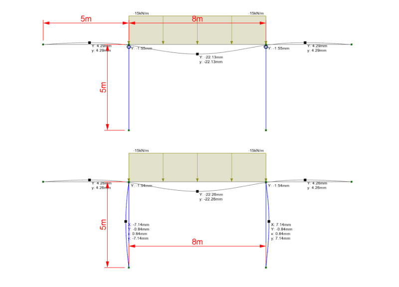
It took me about 5 minute to draw this up:
Untitled_zk9fjm.png


Same loading, same members, realistic member sizes, acceptable beam deflection. In one case the columns are bending like bananas in an unacceptable manner the other they are dead straight because they are pinned connections.
 
Some of my clients would disagree.

But I think you are now just arguing to save face. Rather than engaging in reasonable engineering discussion so I'm done on this topic.
 
human909 - In your first figure, how do you ensure the beam will rotate while the column does not?

I know this is done "all the time". My concern here is if one designs the column based on no rotation (moment)at the top to a CSR = 1.0, that would be unconservative.

Just my two cents.
 
phamENG - Thanks. I was confused on who were the protagonists and who were the antagonists.

I do residential remodeling and, sometimes, I need a steel beam supported by HSS columns. There is no room (architecturally) for a cap plate and bolts, so I end up using field welds. I like to design to a CSR of 1.0 (sometimes 1.04 if I need it), so I've always been concerned about the HSS sections, usually 3"x3"x3/16". Now, I model them and I feel much more confident. If one did not want to model this arrangement and avoid the concern, one could design the column with a moment of WL^2/12, which would be conservative. Since the columns weigh less than 300 pounds, I can get by with a 2 bolt base plate. The base connection is modeled based on the orientation.
 
SE2607,
I want to piggyback off your post. I thought the OSHA requirement for only (2) anchor bolts was if the entire load supported by the column/post is 300# or less.. Is it only if the column/post itself weighs less? That is a game changer for me if so!
 
Human:

To be fair if you are going to model the top beam/column connection rigid then should probably also model the column base connection as rigid or a rotational spring. Also should probably have a rigid end offset between the beam and column to move the attachment to the beam base, the stiffeners will take care of the panel zone deformations.

Your model deflections for the beam are actually quite similar so it would seem that in isolation designing the beam as pin-pin would be accurate.

Not trying to discount the concerns with the column response and like the envelope approach.
 
Jeb - OSHA doesn't care about the finished structure, just the safety of the iron workers while they're erecting it. It's just the weight of the column so it can have some fixity between the time the crane lets go and temporary guys or braces are erected.
 
WesternJeb I believe that is true. I still put a note on my drawings that the column shall be braced until the structure is complete.
 
human909 said:
But I think you are now just arguing to save face. Rather than engaging in reasonable engineering discussion so I'm done on this topic.

The lateral deflection of the column at midheight is 7.14 mm. The height of the column is 5 m, or 5000 mm. The deflection of the column at midheight is H/700, which is well within the allowable deflection limit for any building material, including masonry.

If you wish to go through the exercise of designing this as a rigid frame, I have no problem with that. It will be more accurate than assuming the top of the column is pinned. My point is if you assume the top of the column is pinned, it won't make enough difference to justify the more sophisticated analysis.

DaveAtkins
 
@OP If you want to 'release' the moments you need to have a true pin see human909's vociferous explanation above and in the many other posts on this forum.

Seems like since you are asking about releasing the moment means that you have already determined the detrimental nature of moment transfer here. Without further context its tough to answer your question completely.

@human909 I hear what you are saying. I won't take these connections for granted in the future.
 
Great find Slickdeals. That is pretty hard to argue with from a design standpoint. That is clear cut enough, from a well respected source, to prevent any sort of negligent claim to be made against someone for assume it acts as a pin.

Risaconnection actually implemented this connection in their most recent update of the program, and they put it under the "moment" section, and allow for moments to be input as forces. It seems like this varies widely among respected companies.
 
Status
Not open for further replies.
Back
Top