Navigation
Install the app
How to install the app on iOS
Follow along with the video below to see how to install our site as a web app on your home screen.
Note: This feature may not be available in some browsers.
More options
Style variation
-
Congratulations MintJulep on being selected by the Eng-Tips community for having the most helpful posts in the forums last week. Way to Go!
You are using an out of date browser. It may not display this or other websites correctly.
You should upgrade or use an alternative browser.
You should upgrade or use an alternative browser.
Cap plate for Pipe - How can release moments? 18
- Thread starter X4vier
- Start date
- Status
- Not open for further replies.
milkshakelake
Structural
@human909 If it were a column under a cantilever beam for a balcony or some small load, would you still apply a rigorous analysis or let it go as pinned?
Lomarandil
Structural
I think stating that the connection need not transfer moment is potentially different from saying that the connection will not transfer moment.
So much for me being done on this topic. ![[3eyes] [3eyes] [3eyes]](/data/assets/smilies/3eyes.gif)
This isn't new engineering. Engineers have known about the importance of pinned connections for centuries. It is just good judgement or good analysis that will reveal when it matters and when you can just forget about it.
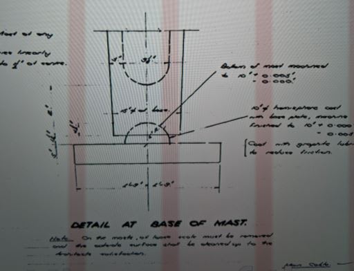
I've posted this previously but I'll post this again. This is the base connection from a 1956. The structure was prone to larger than average deflections and the column was designed to attract minimal moment. So they used a ball and socket joint.


![[3eyes] [3eyes] [3eyes]](/data/assets/smilies/3eyes.gif)
True. I can't argue with that, you are correct. It was a quick model to show the point graphically. As far as base connections go I agree, I have also argued and modelled the behaviour of typical 'pinned' base connections which can readily be semi-rigid or rigidly connected to the footing. The footing however might behave in a pinned fashion for higher loads.Celt83 said:Human:
To be fair if you are going to model the top beam/column connection rigid then should probably also model the column base connection as rigid or a rotational spring. Also should probably have a rigid end offset between the beam and column to move the attachment to the beam base, the stiffeners will take care of the panel zone deformations.
I disagree. Just because minimal moment is being transferred (which is the corollary of minimal change in deflection) doesn't necessarily mean CURVATURE isn't being transferred. It is this curvature and the associated column deflections that are the issue I have been highlighting. It is also and issue I've seen in the field with my eyes, as has WesternJeb. It does not look impressive when the column has visible bend under simple dead load.Celt83 said:Your model deflections for the beam are actually quite similar so it would seem that in isolation designing the beam as pin-pin would be accurate.
I perform the envelope approach if I'm at all concerned. Regarding the column capacity, I've explored in depth previously on eng-tips, most of the time the what you lose in capacity in additional column moments you gain in capacity in reduced effective length.Celt83 said:Not trying to discount the concerns with the column response and like the envelope approach.
I'd normally design things as pinned and quickly move on. I have no problem with that approach without rigorous analysis only if you are "eyes wide open" regard the assumptions you are making and the potential consequences. Us structural engineers make simplifying assumptions all the time, sometimes knowingly sometimes unknowingly. But if we make such an assumption in the wrong circumstance then there can be issues. This is where engineering judgment comes into things.milkshakelake said:@human909 If it were a column under a cantilever beam for a balcony or some small load, would you still apply a rigorous analysis or let it go as pinned?
This isn't new engineering. Engineers have known about the importance of pinned connections for centuries. It is just good judgement or good analysis that will reveal when it matters and when you can just forget about it.
I've posted this previously but I'll post this again. This is the base connection from a 1956. The structure was prone to larger than average deflections and the column was designed to attract minimal moment. So they used a ball and socket joint.


-
1
- #44
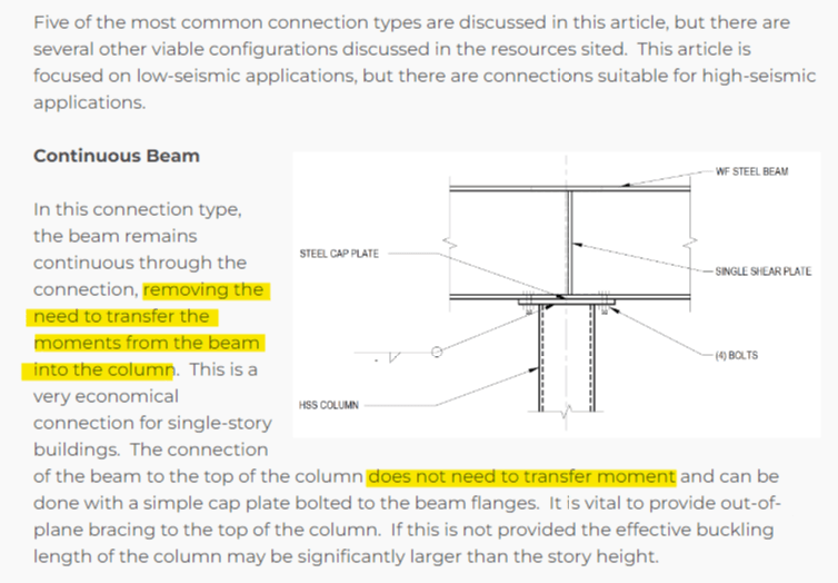
I put no stock in the blurb shown below when it comes to this debate.
What the STI blurb is saying (poorly) is that, with the beam continuous, the designer can obtain the lion's share of the benefits of continuous framing without the need for a beam-column moment connection.
The STI blurb is not a carte blanche endorsement that it is always and forever ok to ignore incidental fixity at these connections.

X4Vier said:Cap plate for Pipe - How can release moments?
1) Accept that, in the real world, there will always be some moment transfer. Even with no welds or bolts, the connection will transfer some moment as a result of the connection being prestressed by the load.
2) Accept that structural engineering is about the moderately intelligent, rough proportioning of things. We "know" nothing and need to be honest with ourselves about that. I'm looking at you John Snow.
3) A skilled designer keeps the moment transferred through the joint small by exerting intelligent control over the relative member stiffnesses. In many applications, a stiff beam run over top of a slender column will wind up transferring little moment through the beam-column joint. Software has become a problem in this regard. Designers tend to build their models and then just push the "optimize weight" button or whatever. This is how you wind up with the odd W6 beam run over top of an TS8 column and creating a joint moment transfer problem. This doesn't often happen to engineers that know their craft. I believe that DaveAtkins and driftLimiter have both alluded to this same concept to some extent.
4) Recognize that the governing mode of failure for many gravity columns is not cross sectional stress but, rather, inelastic buckling. In many of the scenarios where these types of connections are used, the same connection that exerts a bit of moment on the columns will also serve to rotationally restrain the columns at the joint. So K=0.7-ish rather than K=1.0 or whatever.
Kootk said:In many of the scenarios where these types of connections are used, the same connection that exerts a bit of moment on the columns will also serve to rotationally restrain the columns at the joint. So K=0.7-ish rather than K=1.0 or whatever.
Yes I've wondered about this many times but not got to the bottom of it. Perhaps it's fine after all - with any induced moment being more than made up for by the additional fixity? If we have a true pin joint, and we have ductile members, can we genuinely weaken the structure by locking the joint?
milkshakelake
Structural
KootK said:Recognize that the governing mode of failure for many gravity columns is not cross sectional stress but, rather, inelastic buckling.
When you have combined axial compression w/ slender buckling and flexure, with some columns being proportioned barely enough for bending (say HSS4x4), the bending will overtake the buckling.
Tomfh said:If we have a true pin joint, and we have ductile members, can we genuinely weaken the structure by locking the joint?
Yes, by overloading on flexure.
Edit: On second thought, it's probably a rare case. I'll try the enveloped approach on my next project and see if this kind of issue ever pops up.
KootK - I agree with all of your points. Unfortunately (or maybe fortunately), our work is reviewed by others and we have to defend the design, sometimes when there is a structural failure and not a failure associated with the fixity conditions assumed at the connections.
Tomfh said:Perhaps it's fine after all - with any induced moment being more than made up for by the additional fixity?
Exactly. Moreover, when the column starts to move / buckle, that movement itself will tend to reduce the applied moment.
Tomfh said:If we have a true pin joint, and we have ductile members, can we genuinely weaken the structure by locking the joint?
I would say not. In fact, that very statement is one of the key tenets of steel connection design. Unfortunately, in steel, there's often some damn thing kicking around that can buckle before full plasticity can be achieved. It's quite obnoxious really...
SE2607 said:Unfortunately (or maybe fortunately), our work is reviewed by others and we have to defend the design...
That WAS me defending the design practice of assuming a pinned connection in many common design scenarios. And I'd be happy to stand by that in any court in the land. When thoughtful engineers cease to be at liberty to do thoughtful things, engineering ceases to be a profession in any meaningful sense.
milkshakelake said:When you have combined axial compression w/ slender buckling and flexure, with some columns being proportioned barely enough for bending (say HSS4x4), the bending will overtake the buckling.
I don't buy it.
1) For these types of situations, when the column starts to buckle, that motion will relieve the self limiting moment applied through the connection.
2) Any structural engineer who throws significant axial into a slender column already maxed out in flexure doesn't deserve the title.
I need to get back to work. I think I'm in agreement with most of the discussion in the last few posts. I will respond to this however.
I just ran a test on the model in my example above I kept increasing the loads until a column failed. The FIXED columns failed at a load 10% less than the PINNED columns. Now the way I design columns this doesn't get me worried, but others may differ.
**EDIT: I just realised that my answer doesn't take into account plastic ductility which you specifically mentioned. The FIXED column probably has more strength in it despite the code checks due to this.
Yes and no. As I said before normally the benefit of reduced effective length can offset the increase demand from the moment. However this really is a case by case basis, if you are close to the line then a rigid joint can put you over the line.Tomfh said:If we have a true pin joint, and we have ductile members, can we genuinely weaken the structure by locking the joint?
I just ran a test on the model in my example above I kept increasing the loads until a column failed. The FIXED columns failed at a load 10% less than the PINNED columns. Now the way I design columns this doesn't get me worried, but others may differ.
**EDIT: I just realised that my answer doesn't take into account plastic ductility which you specifically mentioned. The FIXED column probably has more strength in it despite the code checks due to this.
-
1
- #53
I'm late to the party.
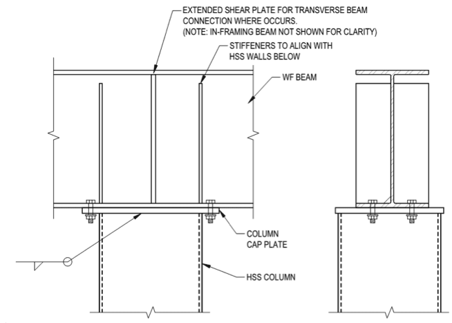
FWIW every firm I've worked for (reputable firms) would design the members as if there's a hinge at the top of the column and create a non fully-restrained moment connection by using:
1. a non-thick cap plate;
2. non-large bolts; and
3. one set of stiffeners at the column centerline.
If the detail had a beefy cap plate, large bolts, and two sets of stiffeners like shown in the OP, then I might take the continuity more seriously.
WesternJeb
Structural
I can get behind 271828's approach with the wimpy cap plate and only one stiffener. My only concern is you are counting on a member to potentially yield while deflecting in order to justify the release of the moment. The beam rotation has to go somewhere, and having it dissipate in the cap plate by the time it gets to the column seems suspect to me after a few cycles of heavy snow loading or a bridge crane going to the end of a runway.
Also a serviceability thing to me. If I see a cap plate looking all wonky while on site, I am panicking, when in reality it might be saving the structure.
Also a serviceability thing to me. If I see a cap plate looking all wonky while on site, I am panicking, when in reality it might be saving the structure.
One thing to consider is if the connection is continuous then the column K is less than one. Also, column base plate stiffness is typically not included.
One could use Gbot=10 and head over to the alignment charts. That is usually conservatively neglected.
I bet the calcs with M=0 and K=1 would be about the same as with M>0 and K<1.
Let's not split gnat hairs. Lol
One could use Gbot=10 and head over to the alignment charts. That is usually conservatively neglected.
I bet the calcs with M=0 and K=1 would be about the same as with M>0 and K<1.
Let's not split gnat hairs. Lol
driftLimiter
Structural
Round and round we go, just like the proverbial hinge connection.
WesternJeb
Structural
phamENG said:too bad we're all fixed in our ways...
Hazza!!!
271828 said:FWIW every firm I've worked for (reputable firms) would design the members as if there's a hinge at the top of the column and create a non fully-restrained moment connection by using:
1. a non-thick cap plate;
2. non-large bolts; and
3. one set of stiffeners at the column centerline.
If the detail had a beefy cap plate, large bolts, and two sets of stiffeners like shown in the OP, then I might take the continuity more seriously.
Same for the firms that I've worked for. That said, I feel that approach serves mainly to obfuscate the important truth of the situation which I feel is this:
In many practical situations, appropriate joint modelling has more to do with what's going with the members coming into the joint than with the restraint offered by the joint itself.
Even a "wimpy" beam over column connection will transmit plenty of moment before something starts to give way. That, particularly, when one considers the joint prestressing effect.
With regard to the stiffeners:
a) A single pair is an appropriate, economical choice if the purpose of the stiffeners is rollover resistance, as it often is with small scale stuff.
b) A double pair is much better if the purpose of the stiffeners is transferring a significant column axial load into the beam. For this, one obviously wants the stiffeners over the parallel HSS walls.
c) I feel that stiffener selection should be informed by [a] and alone, without any regard to attempting to create a faux pin. I see little point in sacrificing legitimate design goals for others that cannot be reasonably achieved.
- Status
- Not open for further replies.
Similar threads
- Question
- Replies
- 10
- Views
- 2K
- Question
- Replies
- 23
- Views
- 8K
- Question
- Replies
- 4
- Views
- 9K
- Question
- Replies
- 5
- Views
- 951
- Replies
- 3
- Views
- 8K

