Eng-Tips is the largest engineering community on the Internet

Intelligent Work Forums for Engineering Professionals

Cap plate for Pipe - How can release moments? 18

Status
Not open for further replies.

X4vier

Civil/Environmental
Feb 24, 2018
152
0
0
CO
Cap plate for Pipe - How can release moments?
Typical cap plates for pipes will have bolts around the pipe, is there a way to release moments in that type of cap plate?
fig-1-e1589488474461_jm1p7r.png

Thanks.
 
Replies continue below

Recommended for you

milkshakelake said:
Sorry, missed this comment in the maelstrom of things. The quote button is like 4 steps to the right of "image", 6 steps to the left of "preview" when you're typing a reply.
Thanks!

DaveAtkins said:
have never heard of a column like this failing in axial plus bending due to ignoring the moment in the column
My response to this as well as comments I've heard (mostly from contractors) about a design being "over engineered" is this: Every structure standing today is over engineered. In reality, particularly with most of the structures I've worked on, the critical loading condition is roof live load which the structure will only experience a few times in its life, namely during construction, during a re-roof or during a fire.
 
KootK said:
Rescind! Or it's pistols at first light...

You didn't say whose first light, so I hope you don't mind that I didn't show up. After all, it was 23 degrees here this morning and I didn't want to stand around long enough to see if you'd show.

After re-reading your post a couple times, I see the logic. So I will offer my apology and rescind my criticism...some of it, anyway.

KootK said:
Is that true? That's really what you are doing in your practice and is the message that you want to be putting out into the world with respect to your understanding of what the standard of care is here?

In a word - yes. If I model something like this in a 3D program, I always put these in as fixed joints. The amount of moment transferred is dependent upon the stiffness of the members, as we've discussed. If I do it by it hand, I typically assume the beam is simply supported, and check the angle of rotation at the connection. I can back out a moment in the column based on its rotation. Whether the actual moment transferred is 3k-ft or 300k-ft, I proportion the connection for that moment. I understand that the standard of care is lower than what I do. That's sort of my MO in as many things as I can manage. And to be honest, I don't get enough steel jobs...so when I get to do one I try to enjoy it.

MSL - what is going on in that picture? Was there a fire?

Dave - that's the Gerber system. As steel got cheaper and labor got more expensive, it fell out of favor for the reasons you stated. I spent some time doing lots of renovations/retrofits of shopping centers built between 1930 and 1990, so I got real familiar with it.
 
This is a great discussion. I can't help but agree with a lot of the points by both DaveAtkins and human909.

For what it's worth, I've often thought that modeling a structure with pinned connections versus fixed or partially fixed would almost always result in a conservative design.
 
phamENG said:
So if we fail to design the connection for the appropriate moment that is transferring through the joint, you can pop the bolts with the added tension from prying, we could yield the cap plate, or do any number of things that could hurt the connection's ability to remain stable even just as a "shear" connection.

But that's the whole point right, using a plate thin enough that it will yield before anything else happens. Almost all of the "pinned" connections in our structural toolbox are based on some sort of localized yielding. This is exactly what was being alluded to when this was posted earlier:


KootK said:
271828 said:
FWIW every firm I've worked for (reputable firms) would design the members as if there's a hinge at the top of the column and create a non fully-restrained moment connection by using:

1. a non-thick cap plate;
2. non-large bolts; and
3. one set of stiffeners at the column centerline.

If the detail had a beefy cap plate, large bolts, and two sets of stiffeners like shown in the OP, then I might take the continuity more seriously.

Same for the firms that I've worked for. That said, I feel that approach serves mainly to obfuscate the important truth of the situation which I feel is this:

In many practical situations, appropriate joint modelling has more to do with what's going with the members coming into the joint than with the restraint offered by the joint itself.

I have no problem with treating this as a pinned connection in a structural model, I wouldn't do it blindly however. I would know that the rotation of the joint is self limiting based on the stiffness of the beam and I would have done some kind of calc that I know the plate will yield before it becomes an issue of overstressing the bolts in tension. Just like a shear tab (or the web it connects to) has a maximum thickness to prevent bolts being sheared before bolt plowing (local yielding) can happen, your cap plate would need a maximum thickness to ensure it yields before anything detrimental happens to the bolt. This isn't a calc you would do for every situation, this is a calc you would do once, then you know that for a cap plate with (4) 3/4" bolts that are 2" away from the column face, you need to keep the plate below 1/2" thick (or whatever it ends up being)
 
Eng16080 - that's the case in most instances, but as with all rules of thumb or simplifications, there are exceptions. With a pin comes rotation. With rotation comes deformation in connections. Can the connection, or more specifically the components of the connection, handle those deformations?

Then you have incidental moments from eccentricity and fixity that have to be accounted for. In most cases, these aren't a problem. The trick is being able to recognize when they are or when they could be.
 
human909 said:
Your initial claim of simply assuming away moment transfer is what started the debate. And from my perspective it remains absurd after dozens of posts as it did originally.

You are entitled to your opinion, and your method of analyzing this type of structure. As can be seen throughout this thread (in the comments by many structural engineers), as well as in the recommendations from Steel Tube Institute, my way of designing this type of connection is also accepted engineering practice.

"I design a lot of similar columns to be pinned when they're partially fixed in reality."

"I see connections like that taken as pinned all the time."

"That is pretty hard to argue with from a design standpoint. That is clear cut enough, from a well respected source, to prevent any sort of negligent claim to be made against someone for assume it acts as a pin."

"I'm mostly with Dave on this one. In 20+ years of practice I could count on one hand the number times that I've encountered interior "posts" that I felt warranted explicit attention with respect to incidental moment of the kind contemplated in this thread."


DaveAtkins
 
dauwerda - I can get behind that. But it seems like a lot of work with limited scope.

A shear tab is one thing - ensuring the ductility comes down to the weld strength, bolt size/strength, and the plate thickness. It's pretty easy to match weld size to plate thickness to a bolt size (if standard spacing is used) so all you have to do is pick the size and number of bolts and your connection is designed. And bolt plowing an yielding in those connections is supposed to be an ultimate load condition, is it not? At service loads, we shouldn't see any significant deformation of the joint. (AISC and/or authors in their publications has/have advocated for using inherent stiffness of shear tabs for accounting for reduced deflections under service loads in the past - I'm not really prepared for that, though...)

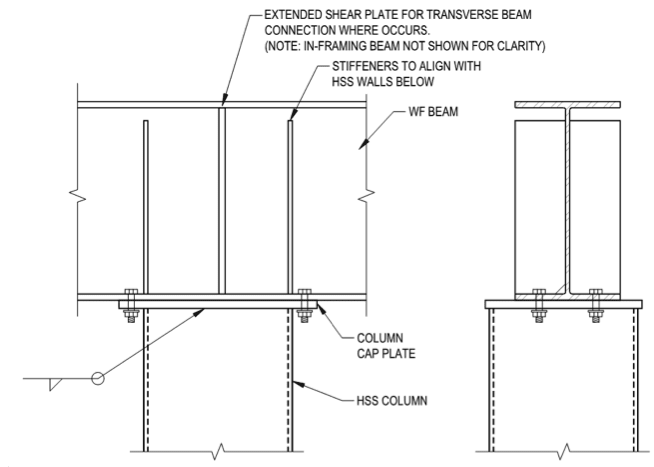
With this connection, you have the column to cap plate weld, cap plate, cap plate plate to beam flange bolts, prying the cap plate and the beam flange. The effort to find a set of combinations of column side wall dimension, cap plate thickness, beam flange thickness, weld size, bolt size, and bolt spacing that will ensure you get yielding in the cap plate before any other non-ductile failure seems like a lot of work. A simple calc sheet that can calculate incidental moment transfer and proportion the joint for the actual loading it will see seems easier to me.
 
phamENG - while I don't disagree with you, I would be curious to see an example of a structure which does not meet my hypothesis that:

Hypothesis: A structure designed with pinned connections versus fixed or partially fixed will result in a conservative design.

I see above that human909 has an example initially claiming to meet this condition, but the comment was later edited to the contrary.
 
This is such a great discussion. I've been taught and have been using the same assumptions as 271828 pointed out. I'm actually looking at a similar scenario for a residential remodel, except everything is welded, no bolts with a thin cap plate. I thought it was initially a no brainer, but this thread is making me reconsider a few things...
 
Eng16080 said:
I would be curious to see an example of a structure which does not meet my hypothesis that:

Hypothesis: A structure designed with pinned connections versus fixed or partially fixed will result in a conservative design.
I would like to take you up on that challenge, when I get a little bit of free time. I do fairly simple structures (residential remodeling), but I occasionally run into a situation where I need a steel beam because a wood beam would not accommodate the architecture. I support these on HSS 3"x3"s. I've always looked at this condition as pinned end, but now that I have a new "toy", I've modeled it. As pointed out, it's entirely possible that the resulting moment in the top of the column is compensated for a k = 1.0 to a k ~ 0.7, which I don't disagree. I've book marked this thread and will come back to it when I get a little time, using a "real world" example, rather than extrapolating from anecdotal and often outdated references. What I will do is model based on a fixed connection and adjust the loadings/members so that I get a CSR = 1.0. Then, I will change the model to pinned connection and see what the resulting CSR is. I'm truly interested in this result. Of course, there is a resulting shear at the base if it is a moment connection which does not exist if it's a pinned connection, but I don't anticipate neglecting this shear would be a problem. Just about any two anchors should resist the resulting shears, again, in the types of structures I deal with on a daily basis.
 
Another data point. There was a similar thread several years back. At that time, I went back and looked at many of our previous designs with fixed and pinned connections. Due to the stiffness of the beams, in no case did we discover any problems with the column design with the minimal moment applied. And we never had a column deflection issue.
 
SE2607 - Challenge accepted. I'm curious myself.

SE2607 said:
What I will do is model based on a fixed connection and adjust the loadings/members so that I get a CSR = 1.0. Then, I will change the model to pinned connection and see what the resulting CSR is.
This however, is not what my hypothesis is. It's that a code compliant structure designed assuming pinned connections would be conservative if the connections were actually fixed or partially fixed. So, you would first design it with pinned connection to get a CSR = 1.0 and from there you would change the connections to fixed without changing anything else.

Okay, now that I'm typing this, I can think of a scenario where my hypothesis fails which is a series of simply supported beams with lateral bracing at the top (but not bottom) being changed to a continuous beam. The beam could fail in the fixed condition due to a lack of lateral bracing where negative moments occur.


Either way, I'm curious whether the CSR goes up or down going from fixed to pinned or pinned to fixed, considering the change of k_col.
 
I am way too obsessed with this...

I ran a Gerber frame on RISA-3D. 30' column spacing, 12' high columns. I put 1.2 KLF load on the beams, for the D + S load combination.

Even though the columns deflect, they do not receive any moment. The moment in the cantilever equals the moment in the backspan. So maybe we are arguing over nothing?

Moment_Diagram_xlhzk1.jpg


Deflected_Shape_gycmor.jpg


DaveAtkins
 
I stand corrected. There is a small moment transferred to the column (1.8 kip-ft). You can see that in the moment diagram above, but it is easy to miss because it does not show up graphically. If I load the middle bay with only dead load, the moment on the column becomes 3.5 kip-ft.

DaveAtkins
 
It's fuzzy, but it looks like there is 1.8 ft-kips of moment at the top of the center columns and 3.1 ft-kips at the outside columns.

*Edit, looks like Dave beat me to it.*
 
Dave - Are you sure that the column axes aren't turned 90 degrees such that RISA doesn't show any moments on your display? (Z vs. Y moments)
Hooke's Law - if there's deflection there's moment.


Status
Not open for further replies.
Back
Top