Navigation
Install the app
How to install the app on iOS
Follow along with the video below to see how to install our site as a web app on your home screen.
Note: This feature may not be available in some browsers.
More options
Style variation
-
Congratulations MintJulep on being selected by the Eng-Tips community for having the most helpful posts in the forums last week. Way to Go!
You are using an out of date browser. It may not display this or other websites correctly.
You should upgrade or use an alternative browser.
You should upgrade or use an alternative browser.
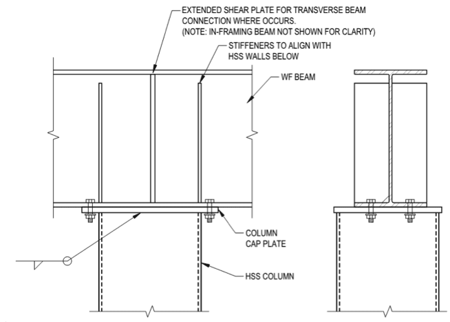
Cap plate for Pipe - How can release moments? 18
- Thread starter X4vier
- Start date
- Status
- Not open for further replies.
-
1
- #121
I believe so. A true hinge is just a single failure point. Bolted shear splice connections on girders have several bolts, so there's a trade off of partial fixity and redundancy. I was trying to provide an example to back up driftLimiter's point about where we draw the line in our simplifications vs reality. The important point is that we should all be cognizant of the true behavior of structures and the reasoning behind generally accepted design simplifications. Then we know where the guardrails are and when to abandon simplifications in certain siutations when they aren't appropriate or conservative.
bones206 said:The important point is that we should all be cognizant of the true behavior of structures and the reasoning behind generally accepted design simplifications. Then we know where the guardrails are and when to abandon simplifications in certain siutations when they aren't appropriate or conservative.
Well said.
Agreed. With phamENG.
You just need to be aware of the assumptions you are making and be aware that by making some assumptions your are implicitly ignoring some effects on your structure. We do this all the time. Our codes do this all the time, sometimes explicitly, sometimes implicitly.
But don't stick you head in the sand and say that because you assume it, then it must be true.
Like most engineers here I model pins or rigid connections and mostly the former. I'm aware that almost all of my pins aren't true pins and also my rigid connection often are not fully rigid. When I find something that is clearly in-between I have delved deeper if it is in an area where serviceability/capacity really matters.
Well said bones206. That is what I've been trying to hammer home since the start.bones206 said:The important point is that we should all be cognizant of the true behavior of structures and the reasoning behind generally accepted design simplifications. Then we know where the guardrails are and when to abandon simplifications in certain siutations when they aren't appropriate or conservative.
No. As repeatedly said by me and again said possibly more clearly by bon206. Nobody is implying that "we can't model pins .... because they are not true pins". Nobody has said that, and that is a misrepresentation of what I and others have said.driftlimiter said:If we buy into this too much we can't model pins anywhere simply because they are not true pins. We have to think about partial moment connections everywhere. Years of practice essentially amount to "ignoring reality".
You just need to be aware of the assumptions you are making and be aware that by making some assumptions your are implicitly ignoring some effects on your structure. We do this all the time. Our codes do this all the time, sometimes explicitly, sometimes implicitly.
But don't stick you head in the sand and say that because you assume it, then it must be true.
Like most engineers here I model pins or rigid connections and mostly the former. I'm aware that almost all of my pins aren't true pins and also my rigid connection often are not fully rigid. When I find something that is clearly in-between I have delved deeper if it is in an area where serviceability/capacity really matters.
phamENG said:In a word - yes. I can back out a moment in the column based on its rotation. Whether the actual moment transferred is 3k-ft or 300k-ft, I proportion the connection for that moment.
Proportioning the connections for that moment for every beam over post condition that you specify sounds like a lot of work. How are you accomplishing that efficiently? RISA Connection? Sexy SMath spreadsheet?
Are you doing something similar where beams connect to posts with shear tabs or clip angles? Those connections also see incidental moment of course.
This thread is very interesting and brought back one specific incident. At the end of my career I was brought back out of retirement to work on an industrial rework project on a building built in the early 1970’s which I had experience from that time; not this specific building.
In the next cubicle was a new engineer with a little over one year of experience. I heard them talking with a few contemporaries that they had modeled a large two unequal span beam with a short W8 interior column support. The column failed. Every time the column size was increased, it got more moment and failed again. Finally, the last young engineer said “have you asked Gary?”
When asked, I went to that cubicle. As I had heard all of the conversations, I asked if they had ever learned moment distribution. They hadn’t as computers were being used in their college years. This column was so short that its stiffness attracted a disproportionate amount of the unbalanced moments. Going back to the first W8 size with pinned joints,both top and bottom, and it worked. W8 column with 10 inch cap plate and two bolts at the column centerline would not transfer a lot of moment. The beam was a W27 or W24; I don’t remember explicitly.
Having started my career with a slide rule, I generally used conservative loads and did not worry as long as my members were kept less than 1.0.
gjc
-
1
- #126
driftLimiter
Structural
human909 while I understand precisely what you are saying. I believe that you have taken the approach here right from the start.
Did I say that I find reality odd, no. Did I say because I see it all the time it must be true, no. You have assumed that this assumption indicates a fundamental lack of understanding of reality. When in fact it seems like most people on this thread both acknowledge the reality of moment transfer, and regularly design these connections as pinned.
It was simply stated by Dave to design the connection as if it was pinned. No one ever said there is no moment. It seems that, quite combatively you have interpreted this to mean that someone is claiming there is no moment there.
Seems like the original suggestion holds up in most cases for buildings. And the practice of design history backs that up.
That all being said, I appreciate the rigor you put into this work and I for one will not think so lightly about this particular assumption in the future.
human909 said:Quote (driftLimiter)
This "not a pinned connection" absolutism is odd. I see connections like that taken as pinned all the time.
Why do you find the reality odd? And why do you think that just because "you see it all the time" make it true?
Did I say that I find reality odd, no. Did I say because I see it all the time it must be true, no. You have assumed that this assumption indicates a fundamental lack of understanding of reality. When in fact it seems like most people on this thread both acknowledge the reality of moment transfer, and regularly design these connections as pinned.
It was simply stated by Dave to design the connection as if it was pinned. No one ever said there is no moment. It seems that, quite combatively you have interpreted this to mean that someone is claiming there is no moment there.
Seems like the original suggestion holds up in most cases for buildings. And the practice of design history backs that up.
That all being said, I appreciate the rigor you put into this work and I for one will not think so lightly about this particular assumption in the future.
Lately I've been using RISA Connection. I used to have a spreadsheet that would do it nicely, but lost it when I left my last firm.
I don't like 'typical details.' This was one that always bugged me. A shear tab is easy, and all the parts are easy to check (or pull from the manual). When I looked into designing these as a shear connection...there are a lot of things that are just...there. If it's a shear connection, what size bolts do you need? How thick should the plate be? What size weld? If somebody ever challenged on me on why I put 3/4" bolts in with a 1/4" plate...I'd just have to shrug my shoulders. I didn't like that, so I decided to just consider the real moment.
I'm not doing it for shear tabs. While they do see incidental moment, they are intentionally proportioned to release that load and rotate without failing the column. While one could theoretically do the same with this....as I mentioned above that seems like a lot of work. And doing that with a connection that is prying doesn't feel right to me. Maybe I could get over it, but...nah.
It's probably also worth noting that these aren't super common connections. It's not like I'm designing 27 of them on each project. One every 8 houses, maybe. I don't get a lot of steel design these days, so that's about it. But when I was doing more steel...one every 2 or 3 projects? I usually try to avoid them unless I really need to squeeze a few inches of clearance out of a roof system.
Which on it's own isn't a problem. However when that statement is in the context of an explicit question on how to release the moment in the connection then it IS a problem because it doesn't achieve the goal.driftLimiter said:It was simply stated by Dave to design the connection as if it was pinned.
dauwerda said:I have no problem with treating this as a pinned connection in a structural model, I wouldn't do it blindly however.
I don't feel that I do it blindly. I see to it that my Ib/Lb is several multiples of Ic/Lc and leave it at that.
dauwerda said:I would know that the rotation of the joint is self limiting based on the stiffness of the beam and I would have done some kind of calc that I know the plate will yield before it becomes an issue of overstressing the bolts in tension.
To each his own. I don't feel that even that level of effort is necessary. My minimums for pinned cap plate connections for anything resembling serious construction are a 5/8" cap plate and 5/8" diameter bolts. Lots, and lots, and lots of experience with that (mine and others) has produced to problems that I am aware of.
In general, I feel that it is important that we recognize that structural engineering isn't about checking every possible failure mode and precluding it. Structural engineering is about checking the things that have caused us problems in the past. We are very much a reactive profession in that regard, for better or for worse. And this, simply, is not something that has been causing bolt fracture problems in properly proportioned frames.
When is the last time that anyone checked vertical -- not diagonal -- shear on a vertical plane in between beam stirrups in a beam without a construction joint? That's something that could happen. But it doesn't, so we don't check it.
driftLimiter
Structural
human909 said:Which on it's own isn't a problem. However when that statement is in the context of an explicit question on how to release the moment in the connection then it IS a problem because it doesn't achieve the goal.
This is a fair point. The lack of input from the OP has allowed this thread to balloon into something else altogether.
So I am curious, if the OP needs to release the moment what recommendation can we offer him?
Ball and Socket at the top of a column?
Some kind of rocker?
Is there a conventional connection that achieves what the OP desires?
Thanks. And it has been my point all along. Though like you say, the thread has ballooned and context is lost. And I could have done a better job of explaining the point.driftLimiter said:This is a fair point.
Yes I'd say a rocker. Which is what I have said before has Smoulder.
For what it is worth I'm now modelling this connection to try to put some numbers on the stiffness. I expect it to be semirigid with low axial loads and close to rigid with high axial loads.
milkshakelake
Structural
This must be the eng-tips world record for a pretty innocuous post starting a storm of controversy with zero input from OP. I think X4vier is gone at this point, scared away by the massive wall of fire.
I need to think more about these connections in the future. My eyes have opened up from blind assumptions.
-If that's not possible, a smooth rod type of connection with grease (kind of like the pin connecting a crane hook) with vertical knife gusset plate.
I need to think more about these connections in the future. My eyes have opened up from blind assumptions.
-Switch it to W8, put the bolts within the flanges.driftLimiter said:if the OP needs to release the moment what recommendation can we offer him?
-If that's not possible, a smooth rod type of connection with grease (kind of like the pin connecting a crane hook) with vertical knife gusset plate.
milkshakelake said:This must be the eng-tips world record for a pretty innocuous post starting a storm of controversy
Was MSL here for the fly braces? thread507-459248
I in no way was trying to say that you were doing it blindly - you are the last person that I would ever accuse of doing anything blindly. So, I'm sorry if my post came across that way.KootK said:I don't feel that I do it blindly. I see to it that my Ib/Lb is several multiples of Ic/Lc and leave it at that.
I agree with you here as well. However, engineering judgement must be based on something, if you have nothing else to go on, run a calculation to make yourself feel comfortable. I also specifically addressed it as the (potential) issue was brought up in the post I was replying to.KootK said:To each his own. I don't feel that even that level of effort is necessary. My minimums for pinned cap plate connections for anything resembling serious construction are a 5/8" cap plate and 5/8" diameter bolts. Lots, and lots, and lots of experience with that (mine and others) has produced to problems that I am aware of.
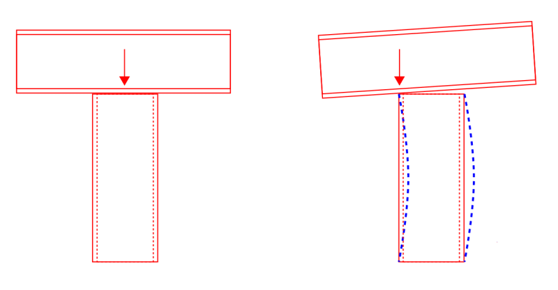
Consider the simplified case of a column without any cap plate or connection to the column whatsoever. As soon as the beam experiences any rotation at this joint there will be a moment induced in the column even if there is no moment transferred from the beam to the column. It is simply a matter of where the beam's reaction occurs relative to the centerline of the column. The only way to prevent this would be to provide an actual pin/rocker/what-have-you. Providing a very flexible cap plate (1/4" thick for example) will not prevent this. Providing a very thick cap plate would increase the induced moment as the reaction moves even further away from column CL.
Similar to how moment is induced in a column in the case of a shear tab welded to the face of the column. For example, RAM Structural System / RAM Steel column design module always considers this eccentricity from the face of the column (d_col/2 + distance from face of col to shear tab bolts). It takes into account the maximum effect caused by a beam loaded fully on one side of the column and no load on the opposite side, or whatever combination of attached members.
Just food for thought. What say the hivemind?

slickdeals
Structural
I think you have all successfully managed to confuse the OP and not provide any useful direction. In all honesty, I don't know if this thread required as many responses and rebuts.
dold said:will be a moment induced in the column even if there is no moment transferred from the beam to the column
The moment induced in the column is moment taken away from the beam. The point of contraflexure is shifted to the point of eccentricity.
MSL said:This must be the eng-tips world record for a pretty innocuous post starting a storm of controversy with zero input from OP.
That's to be expected. The best threads usually have little to do with the needs of the OP. And, often, the OP isn't really in a position with respect to experience or knowledge to go to bat with the heavy hitters of our little cadre.
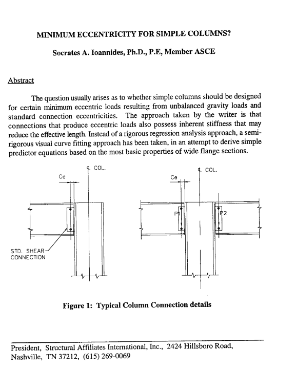
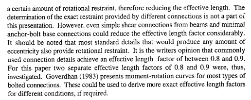
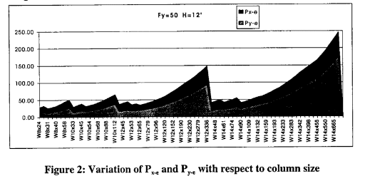
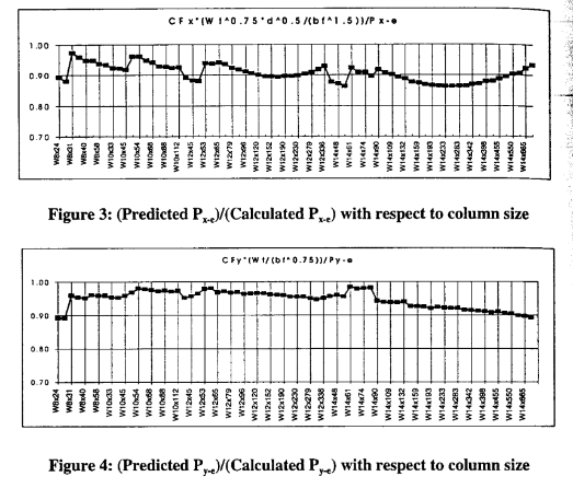
I'm going to post some literature on a related topic: the appropriateness of ignoring column eccentricity for simple beam shear connections. It's not my intent that this be taken as any kind of silver bullet supporting any particular position. It's just information that I feel belongs here and may be of interest to some. I picked up the Ioannides article back in 2000 when I had my first freakout over this.
Steel Interchange article discussing the Ionnides article: Link
Some clips from the Ionnides article which I can supplement if desired (still under copyright). Ionnides put some numbers to things and, effectively, comes to the same conclusion that is evolving here: incidental moments can often, but not always, be ignored.
Needed or not, I'd still prefer to have code provisions similar to some other countries that insist that eccentricity be taken to the bolt line. That kind of stuff is tough to enforce in a marketplace where it's optional however.

DaveAtkins
Structural
I don't regret this thread taking off as it has. We have all learned a lot.
As human909 and others have made clear, I may not have been answering the OP at all. I assumed the OP was designing a beam over column and wanted to neglect the moment in the column, but that may not be what he/she was asking at all.
DaveAtkins
As human909 and others have made clear, I may not have been answering the OP at all. I assumed the OP was designing a beam over column and wanted to neglect the moment in the column, but that may not be what he/she was asking at all.
DaveAtkins
- Status
- Not open for further replies.
Similar threads
- Question
- Replies
- 10
- Views
- 2K
- Question
- Replies
- 23
- Views
- 8K
- Question
- Replies
- 4
- Views
- 9K
- Replies
- 3
- Views
- 8K
- Replies
- 16
- Views
- 6K

