Navigation
Install the app
How to install the app on iOS
Follow along with the video below to see how to install our site as a web app on your home screen.
Note: This feature may not be available in some browsers.
More options
Style variation
-
Congratulations MintJulep on being selected by the Eng-Tips community for having the most helpful posts in the forums last week. Way to Go!
You are using an out of date browser. It may not display this or other websites correctly.
You should upgrade or use an alternative browser.
You should upgrade or use an alternative browser.
Cap plate for Pipe - How can release moments? 18
- Thread starter X4vier
- Start date
- Status
- Not open for further replies.
-
2
- #2
DaveAtkins
Structural
Simply assume there is no moment transfer between beam and column and design the members accordingly.
DaveAtkins
DaveAtkins
No. This is such a big no, that I'm not sure where to begin. You cannot simply just assume away the moment transfer and it will disappear, that sort of logic is mind boggling.DaveAtkins said:Simply assume there is no moment transfer between beam and column and design the members accordingly.
While in some cases having an modelled pin joint behave like in a rigid fashion is conservative, in others it is absolutely not.
First up I'd check the implications of having a rigid or semi rigid connection here. If you are just designing the connection then send the question up the line. When I'm designing connections that I'd prefer to be pinned, but they end up being semi rigid I run the model using both scenarios and check the suitability of both.X4vier said:Cap plate for Pipe - How can release moments?
Thin end plates can accomplish this quite effectively. I've used this approach for HSS beam to beam connections in a recent project. But there I was only transferring shear.X4vier said:Typical cap plates for pipes will have bolts around the pipe, is there a way to release moments in that type of cap plate?
If you used a thin cap plate here you might have issues with your axial load transfer. But it is quite likely that the edge bearing of the beam over the column is sufficient unless axial loads are very high. This solution would be my preference. thin end plates and your job is done. I'd use 6mm and make the plates even wider this allows shear transfer but any moment results in just plate flex. (The presence of axial loads will however cause some moment transfer.)
If axial loads are very high then you may need a rocker type connection. However I really doubt you'd require this unless axial loads are high and you REALLY need a well behaved pin connection.
milkshakelake
Structural
If it's not designed as a moment connection, you might have a plastic hinge in the column due to a moment it wasn't designed for. You can easily solve this by designing the column for that moment. Not as easily, but still very much within the realm of good practice, would be to design the cap plate and bolts for the moment connection. The caveat is that this ends up transferring moment to the base plate, changing stiffness of the structure, and lots of other ill-advised side effects.
If you change the HSS column to a W-shape, you bring out the possibility of using bolts in the cap plate within the flanges, which can be idealized as a pin connection.
I get what DaveAtkins is saying. I design a lot of similar columns to be pinned when they're partially fixed in reality. But those tend to be low axial loads, like a column supporting a balcony or stair landing. In this case, the existence of stiffeners and the proportions of the column make it seem like the axial loads are quite high. So with higher loading, more introspection is needed.
DaveAtkins
Structural
human909 said:No. This is such a big no, that I'm not sure where to begin. You cannot simply just assume away the moment transfer and it will disappear, that sort of logic is mind boggling.
I assume this is a beam cantilevering over a column. If so, then this type of connection is designed as pinned to the top of the column. The bending moment from the cantilever equals the bending moment in the backspan, and no moment is transferred to the column. I am not sure why human909 has a big problem with this, since this is the way it is typically done.
The stiffener plates are probably there to prevent web crippling, although if so there is no need for three plates on each side. One on each side will suffice.
DaveAtkins
WesternJeb
Structural
In no universe do I see this as a pin. If the beam wants to deflect and the bottom flange is restrained via the bolts to top of column, the column will want to "bend over" with it. When it doesn't bend over as the beam goes to deflect, that is restraining rotation.
For it to be a pin, the flanges would have to be able to lift off of the support plate, which they can't.
For it to be a pin, the flanges would have to be able to lift off of the support plate, which they can't.
-
3
- #9
driftLimiter
Structural
This "not a pinned connection" absolutism is odd. I see connections like that taken as pinned all the time.
The ramifications of it being partially fixed could be evaluated if your all concerned. I would want to look at the relative stiffness of the beam and column, as well as any flexibility introduced by the plate to determine how much load this 'fixed' connection's really attracts.
The ramifications of it being partially fixed could be evaluated if your all concerned. I would want to look at the relative stiffness of the beam and column, as well as any flexibility introduced by the plate to determine how much load this 'fixed' connection's really attracts.
-
1
- #11
milkshakelake
Structural
I think OP needs to step in and clear this up with the loading. If the axial load is low, like carrying a small cantilever beam, it doesn't matter whether it's pinned or fixed, does it? If it's a transfer beam carrying like 10 stories, then yeah, it's a big f'in deal.
Driftlimiter said:This "not a pinned connection" absolutism is odd. I see connections like that taken as pinned all the time.
Yes. And generally the moments are small enough that it doesn’t matter. But sometimes it matters.
WesternJeb
Structural
I would like to clarify that most of my experience with this connection has been designing 20 ton bridge cranes that are cantilevered 15' or so from the column. That might bias myself a little bit.. But I still stand that this is a connection that leans to more fixity than pinned.
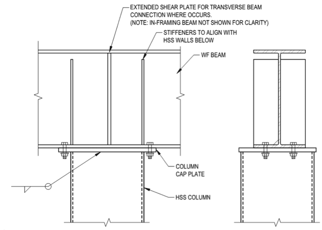
I have seen a steel frame for a church canopy built like this from a contractor without an engineer. The system was a W8 beam spanning 25' between two HSS columns with the connection shown above. Not only was the beam deflecting around 8" in the middle, but both of the columns were also deflecting inward to match the slope of the beam! This screams fixed to me.
I have seen a steel frame for a church canopy built like this from a contractor without an engineer. The system was a W8 beam spanning 25' between two HSS columns with the connection shown above. Not only was the beam deflecting around 8" in the middle, but both of the columns were also deflecting inward to match the slope of the beam! This screams fixed to me.
That is a plainly false assumption. Depending on the loading conditions the beam over the column may not have a 0 degree slope. If it does not have a zero degree slope then it necessarily will transfer moment into the column if the connection is rigid.DaveAtkins said:I assume this is a beam cantilevering over a column. If so, then this type of connection is designed as pinned to the top of the column. The bending moment from the cantilever equals the bending moment in the backspan, and no moment is transferred to the column.
I don't have any problem with this. I have a problem with you ASSUMING away a potential issue by pretending it is a pinned connection when it isn't.DaveAtkins said:I am not sure why human909 has a big problem with this, since this is the way it is typically done.
I've seen slender columns bent like banannas because the continue beams on top transferred some of their moment. It wasn't necessarily a structural integrity issue, but it certainly was an architectural issue.
Exactly.WesternJeb said:In no universe do I see this as a pin. If the beam wants to deflect and the bottom flange is restrained via the bolts to top of column, the column will want to "bend over" with it. When it doesn't bend over as the beam goes to deflect, that is restraining rotation.
For it to be a pin, the flanges would have to be able to lift off of the support plate, which they can't.
Why do you find the reality odd? And why do you think that just because "you see it all the time" make it true?driftLimiter said:This "not a pinned connection" absolutism is odd. I see connections like that taken as pinned all the time.
I'll reiterate. I don't think that it is necessarily an issue to treat rigid/semi-rigid connections as pinned. However it certainly can be an issue.
I don't think scale changes much, scale things up or down and we still largely get the same behaviour.WesternJeb said:I would like to clarify that most of my experience with this connection has been designing 20 ton bridge cranes that are cantilevered 15' or so from the column. That might bias myself a little bit.. But I still stand that this is a connection that leans to more fixity than pinned.
Yep. As above I've seen the same.WesternJeb said:I have seen a steel frame for a church canopy built like this from a contractor without an engineer. The system was a W8 beam spanning 25' between two HSS columns with the connection shown above. Not only was the beam deflecting around 8" in the middle, but both of the columns were also deflecting inward to match the slope of the beam! This screams fixed to me.
Just because it sometimes works doesn't make it always work! For what it is worth the respective size of the beam compared to the column would imply that this column probably won't have any issues. But without the full model we cannot know.
Also do you really think engineers would bother with proper pins if they could get away with always assuming away the moment.

Yes, you can often do it. Yes I often do it. Both no you shouldn't be doing it without considering the consequences of the ACTUALY connection behaviour.
Also a similar discussion a couple of years ago is a close repeat of this discussion.

Yes, you can often do it. Yes I often do it. Both no you shouldn't be doing it without considering the consequences of the ACTUALY connection behaviour.
Also a similar discussion a couple of years ago is a close repeat of this discussion.
WesternJeb
Structural
I think this thread is a great example of why we have safety factors of 1.5-2 on everything, along with statistically unreasonable design loads. It keeps engineers honest, and allows for some of these different design assumptions to be made with minimal repercussions.
Nevertheless, I still believe this is a more fixed than pinned connection. I will compromise and say 75%-25% haha!
Nevertheless, I still believe this is a more fixed than pinned connection. I will compromise and say 75%-25% haha!
-
1
- #19
If you want it to be a 'pinned' connection, assume it's a pin when put together your analysis model (model in the general sense - could be 3D FEM, could be a pencil sketch FBD) and design the beam and column accordingly. Then, once you have the member sizes, re-run it as a moment connection to get the actual moment transferred and verify that everything works. Size the connection as a moment connection for the actual transferred moment. I usually find that the column needs be a bit thicker than when I was assuming a pin, but not always.
This gives you a good bracketed solution and ensures satisfactory behavior of the structure. Because the connection itself is a moment connection (no rotation IN the joint) and, unless you want some ugly deformation in your cap plate and some wicked prying in the bolts, it needs to be designed for it. But the members themselves are typically not stiff enough to restrain rotation OF the joint, so the global behavior isn't really fixed.
This gives you a good bracketed solution and ensures satisfactory behavior of the structure. Because the connection itself is a moment connection (no rotation IN the joint) and, unless you want some ugly deformation in your cap plate and some wicked prying in the bolts, it needs to be designed for it. But the members themselves are typically not stiff enough to restrain rotation OF the joint, so the global behavior isn't really fixed.
-
1
- #20
DaveAtkins
Structural
I agree, good discussion.
I still contend that a tall, slender column will have a relative stiffness so small that the moment in the cantilever will mostly transfer to the much stiffer beam backspan, and not to the column. The column will not attract much moment, and the connection can be treated as pinned. It has less to do with the thickness of the bearing plate and the fact that there are four bolts, and more to do with the relative stiffness between the beam and the column.
And if you are seeing beams and columns deflecting too much, then that is a function of not checking deflection, not a function of assuming a connection is pinned or fixed.
DaveAtkins
- Status
- Not open for further replies.
Similar threads
- Question
- Replies
- 10
- Views
- 2K
- Question
- Replies
- 23
- Views
- 8K
- Question
- Replies
- 4
- Views
- 9K
- Question
- Replies
- 5
- Views
- 963
- Replies
- 3
- Views
- 8K


