Continue to Site

Eng-Tips is the largest engineering community on the Internet

Intelligent Work Forums for Engineering Professionals

  • Congratulations cowski on being selected by the Eng-Tips community for having the most helpful posts in the forums last week. Way to Go!

Complex Hole Callout as a Critical Feature 1

Status
Not open for further replies.

Tom F.

Mechanical
Feb 27, 2019
3
Greeting! There is currently a rather heated discussion between the Design Team and the Quality Inspectors in my company about complex feature callouts that are critical to function. For this example, I am going to use a counterbore hole feature. We use the diamond symbol (♦) to denote critical to function features on our drawings. The design team posits that the entire hole callout should be treated as a single feature and thus requiring a single diamond symbol. The Quality Team is saying that there are 3 different features that make up the hole and if they are all critical to function then they all should have separate diamond symbols.

My question for the community here is, how does your company deal with this type of situation? Also is there any standard governing this?

Thank you.

Tom F.
Rochester, NY


Replies continue below

Recommended for you

Does the specification for the counterbored hole look something like this?
20190227_182800_e8q9ty.jpg
 
Yes. I apologize for not including an image. Here are the two ideas visualized.

264tgz8.png

Design

2mqkkrc.png

Quality

Tom F.
Rochester, NY
 
I don't know what any standards say about this, but since the 2 rows specify different features that are usually produced by separate drilling operations and controlled individually for size and depth, I would put a separate symbol for each row.
 
Tom F.,

I do not understand the concept of critical dimensions. All of my dimensions are critical. If I do not need them to be accurate, I make them sloppy, which puts them well within the manufacturer's capability. If the dimension is easily achieved, there is minimal need for inspection.

If the tolerance is difficult to do, the parts must be inspected, regardless of how important it is. I appreciate it when the fabricator tells me what is difficult. I can look for way to open up the tolerance.

--
JHG
 
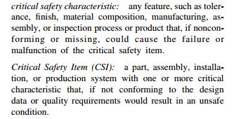
The use of critical dimension / characteristic concept most likely varies between different companies, but from my experience it's often related to safety. I don't have the latest Y14.100 handy, but here is a screenshot from 2000 version of the document:

capture_j8gbae.jpg


In the company I work for we would use 3 different "critical" symbols, if all three characteristics were truly critical. That is mainly because there is a characteristic number (CN) tool in use that automatically flows down all the drawing requirements to a characteristic report. Each of the three characteristics would have its own CNs and if only one of them had the "critical" symbol assigned, only that one would be seen as critical in the characteristic report, which would be against the intent.

But I am pretty sure others may do it differently.
 
drawoh,
From what I can tell the treatment of critical specifications is different from the rest of the specifications from the QA procedures aspect. Whereas the inspection of "non-critical" dimensions is sometimes trusted on the manufacturing division of a company which may decide to skip the inspection of certain dimensions at all to reduce costs since the process is controlled well enough etc., critical dimensions always need to be dealt with by the QA department before the product enters the warehouse. It is believed to reduce the number of customer complaints and eventually do good for the company.
 
It's interesting that Quality is also advocating for a non-zero tolerance on the diameters ;^)

Evan Janeshewski

Axymetrix Quality Engineering Inc.
 
Evan,

They were probably called out at MMC to take advantage of the full bonus tolerance.
 
Tom F.,

Why does your company denote "critical to function features" on drawings? What meaning is this intended to convey, and to whom?

Inspection is generally intended to determine whether an item conforms to its requirements. In that context, I think the concept of "critical requirement" makes a lot more sense than "critical feature". Do your drawings ever designate anything other than requirements as being critical?

I assume ♦R, ♦S, ♦T, etc. are intended to be unique identifiers within a drawing, and that these identifiers will be used in other documents to refer to the associated requirements. If an identifier can refer to a group of requirements, there needs to be a way to determine exactly what that group includes. If each identifier always refers to exactly one requirement, interpretation is greatly simplified. Based on your two images, I think this is a strong argument in favor of your quality team's approach.

What benefit does your design team see in their approach? The three tolerances in the hole callout are essentially independent, so lumping them together seems somewhat strange. You wouldn't expect an inspection report to provide a single result for the group of three tolerances, would you?


I'm getting somewhat off-topic now, but are your images representative of real drawings? The general scheme seems less than ideal. The distinction between the identifiers and the actual specification is not immediately and visually obvious. You could also end up with particularly problematic cases such as "♦S R .90", which looks like a spherical radius, or "♦M 2.5", which looks like a metric thread. It might be better to enclose the identifiers in some unique border, and possibly move them a bit so they don't flow together with the rest of the text.


pylfrm
 
My guess is that R means printed Report required with the item,
T means technological requirement, and S means that statistical (process capability) analysis is needed.
 
... - P - Q - R - S - T - U - V - ...

Otherwise it would be a great coincidence to have one each of three different requirements on separate dimensions of one feature in alphabetic order.

In any case, to the OP, while one might argue that all the dimensions of a feature might be subsumed into a single critical notation, it's beneficial when a feature is found to have failed to specify exactly where the failure occurred. Normally dimensions are given individual identifiers in the QA/QC documentation for just that purpose, but here is a case where Design is demanding something beyond that, so it seems like QA/QC is suggesting that the normal "each one" marking should apply.

Otherwise one could just title the drawing "Critical" and let QA/QC flag non-conformant parts and let design figure out what requirement failed.
 
Sem_D220 said:
drawoh,
From what I can tell the treatment of critical specifications is different from the rest of the specifications from the QA procedures aspect.

I have been in a place where they applied dimensions and tolerances to critical features only. Undimensioned features were to be fabricated to "standard manufacturing tolerances". There was a note on the drawing specifying a profile tolerance for the undimensioned features. The understanding was that the vendors would submit First Article Inspection (FAI) reports, showing inspection of the dimensioned features.

Left to my own devices, I prefer complete drawings. They are not difficult to do. I have just done a Lean Manufacturing White Belt certificate. Inspection is a waste, over processing. It provides no value to the customer. If your tolerances are easily fabricatable by your vendors, there is no need for anything more than occasional checks. If the tolerances that trigger inspection are non-critical, you should re-think your design.

--
JHG
 
pylfrm said:
I'm getting somewhat off-topic now, but are your images representative of real drawings? The general scheme seems less than ideal.
What... having a zero tolerance is less than ideal to you? Come on, can't you make perfect parts?
(kidding of course -- thanks to Evan for first noticing the "perfect" requirement of their diameter of .180!)
 
drawoh,
I can relate to your approach and I see the logic behind it.
However, I would not dismiss the usefulness of the concept of "critical dimensions"
Where I work they are called Key Characteristics and one of the benefits of using them is that they require the QA department to make statistical calculations of process capability for the specifications that are defined as "KC".
Process capability levels can provide useful information both for manufacturing and design. For example, where it is not practical to make a feasible design that can assure a good part/assembly under the worst case tolerances combination at given features or parts, one could evaluate the realistic ranges within which the geometry can vary and evaluate how much "risk" is taken.
 
Thank you all for your responses. This is all great information. The letters are merely identifiers and have no particular meaning. Critical to function in this case simply means that if these features are out of tolerance, the part will fail to assemble/function properly. We have a general tolerance block elsewhere on the drawing. The ±.00 tolerance is an error in precision from my software. It should be ±.002 as in the Quality capture. The only difference in the 2 captures should be the number of ♦s presented.

 
Critical characteristic symbols have been around in the automotive industry for a long time, formalized under the TS16949 technical standard. I was totally against it originally taking the same stance as above that all the dimensions are important and need to be met. However, after living with it for a decade or so I've come to appreciate it. If implemented correctly, all the critical characteristics follow through all the documentation, DFMEA, PFMEA, control plans, etc.

To answer the OP's question, we would use 3 symbols, one for each characteristic in the callout.

The one area that I despise is the non-standardization of the symbols. According to TS16949, you are supposed to use the customers symbols and there is no commonality among auto makers. This makes it hard to have standardized parts that you sell to multiple customers. Also, if your customer does not have their own symbols you are free to create your own.

----------------------------------------

The Help for this program was created in Windows Help format, which depends on a feature that isn't included in this version of Windows.
 
Status
Not open for further replies.

Part and Inventory Search

Sponsor