Continue to Site

Eng-Tips is the largest engineering community on the Internet

Intelligent Work Forums for Engineering Professionals

  • Congratulations waross on being selected by the Eng-Tips community for having the most helpful posts in the forums last week. Way to Go!

Composite Position and Parallelism 2

Status
Not open for further replies.

gregkeez

Mechanical
Feb 28, 2022
6
Hello,

First time posting on here. I'm working on a drawing with a group of holes that I want to control as a pattern using composite position. In the feature control box, the goal of the second line is to control the pattern's parallelism to the two datum holes. Is this the correct way of doing such or would it be something like A | B-C in the feature control box?? The actual part I am working on is not a simple rectangular shape, rather something a little more complex but I figured this was good enough to get my point across. I know I could add another datum to say, the top of the part and have parallelism to that but was wondering if I could do the same thing using composite position.
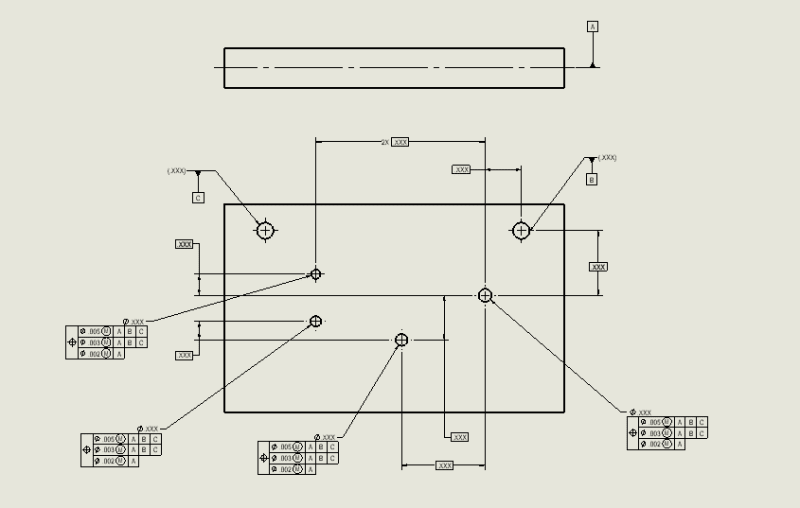

Composite_Position_jxw0v4.png
 
Replies continue below

Recommended for you

gregkeez said:
Datum holes are not threaded.

Sorry, my mistake. I thought there were two sets of lines for each datum hole - solid and dashed.
 
greenimi,
I also don't understand the bit about datum precedence order violation in the second segment.
What concerns you about the constraints of rotational degrees of freedom by the A|B|C references in the second segment the way I described it?
 
gregkeez,

This has not been discussed so far (I omitted it intentionally too and hope that this time I read the drawing correctly ;-]), but the way datum feature symbol A is shown is incorrect per the standard. The symbol shall not be placed on center lines, center points, etc - it needs to indicate a physical feature of the part.
 
pmarc said:
Does it have anything to do with a belief that repetition of the same datum features in the lower segment of composite FCF as specified in the uppermost segment is not allowed?

No. Not at all.
It is allowed and more important, it is even mandatory in some cases.


I am thinking that B by itself in the second segment does nothing. Also C, by itself, as tertiary, does nothing.
But I am not understanding how B|C| --again B secondary and C tertiary--- is able to "do something" in the composite.

Same idea, as in 7-43/2009.
B by itself in the secondary, does nothing....But if C is added (C by itself is able to stop remaining DOF which was not stopped by A)
The main difference between 7-43/2009 and OP's picture is that C is able to stop a rotation a DOF in 7-43

versus

C is not able to stop (again by itself) any (none) DOF's in the OP's picture/ case.


pmarc,

Thank you for pointing that out. On my actual drawing, that centerline is in fact a section line that the datum is placed on. I'm guessing this is also incorrect?
 
greenimi,

B and C only apparently do nothing in the lower segment. Together (B secondary and C tertiary) they assure that the part's relationship to the DRF established from the datum feature simulators A, B, and C is the same in both segments.
 
pmarc,

To clarify on datum A, datum A is actually established on the forging drawing using datum targets and in this case, is just a reference.
 
gregkeez said:
Thank you for pointing that out. On my actual drawing, that centerline is in fact a section line that the datum is placed on. I'm guessing this is also incorrect?

Yes, it sounds like it is also incorrect, but hard to say with 100% certainty without seeing the drawing.
 
gregkeez said:
To clarify on datum A, datum A is actually established on the forging drawing using datum targets and in this case, is just a reference.

OK, in that case it may work.
 
pamrc said:
B and C only apparently do nothing in the lower segment. Together (B secondary and C tertiary) they assure that the part's relationship to the DRF established from the datum feature simulators A, B, and C is the same in both segments.

So, looks like if only A is added in the second segment won't change the meaning nor the definition of the drawing? No need at all for the lower (third) segment.
Do you agree?

What is the point of having 3 segments in this particular application?
 
greenimi said:
So, looks like if only A is added in the second segment won't change the meaning nor the definition of the drawing? No need at all for the lower (third) segment.
Do you agree?

No, I don't agree with that.

The third segment refines spacing between the four features in the pattern and their orientation/perpendicularity to datum A. But it does not constrain rotation of the framework of four tolerance zones in plane A - this is what the second segment is doing.
 
Datums established on other drawings have no effect. They only apply on the drawing level they are defined for.
 
greenimi,

I know the issue that you're referring to here, with the datum features in the 2nd segment that appear to have no effect. I've spent a lot of time studying this, starting more than 10 years ago. You've made my day by asking about it - this gives me the opportunity to shamelessly plug Y14.5.1-2019 Mathematical Definitions of Dimensioning and Tolerancing Principles.

burunduk and pmarc are correct - repeating the A|B|C sequence in the 2nd segment is fine, and that the B and C references actually do affect the constraint. But this would be difficult to conclusively prove using references from Y14.5. There are conflicting explanations in different sections - some are correct, and others are not. One of the main problems has been the interpretation of the following statement from Section 10.5.1 (b):

(2) When datum feature references are specified in a lower segment, the FRTZF is constrained only in rotation relative to the datum reference frame.

The most common interpretation is the one that you arrived at, in which the datum features in the lower segment(s) only constrain rotational DOF's. It follows that if there are no rotational DOF's available that the datum feature is capable of constraining, then that datum feature has no effect. This would be the case for secondary datum feature B in the OP example - datum feature A has already constrained 2 rotations, and B can't constrain the 3rd rotation. Y14.5 actually supports this, in the next paragraph:

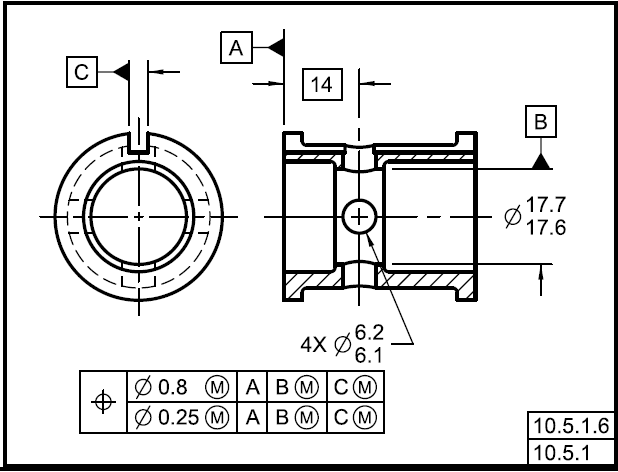
When datum feature references are specified, one or more of the datum feature references specified in the upper segment of the frame are repeated, as applicable, and in the same order of precedence, to constrain rotation of the FRTZF. In some instances, the repeated datum feature references may not constrain any degrees of freedom; however, they are necessary to maintain the identical datum reference frame, such as datum feature B in the lower segment in Figure 10-43.
Fig_10-43_ciye0n.png

Not only does is seem very strange that there would be spurious "placeholder" symbols, if we follow the logic of the underlined statement it doesn't agree with what is shown in the 10-43 "means this" figure. The caption states that "the FRTZF is constrained in rotation to datum plane A, datum axis B, and datum centerplane C". If the reference to feature B really had no effect, then there wouldn't be a datum axis B. The 3rd rotational DOF would just be constrained by datum centerplane C. In fact, the reference to datum feature B does have an effect.

It turns out that there is another way to interpret "the FRTZF is constrained only in rotation relative to the datum reference frame", which turns out to be the correct one (or, at least, one that makes sense with the figures in Y14.5). The datum features in the lower segment constrain rotational and translational DOF's like they normally would, and then the FRTZF is allowed to translate relative to the DRF. So the "rotation only" effect in the lower segment pertains to the "float" of the tolerance zone framework, not the constraint applied by the datum features. The way I like to describe it is that the lower segment of a composite acts kind of like an orientation tolerance for the pattern.

With this logic in mind, here is the progression of constraint for the second segment in the OP example:

A: Constrains rotations u and v, translation Z
B: Constrains translations X and Y
C: Constrains rotation w

Translations are then "floated" for the FRTZF. So both B and C participate in the w rotation - B provides the "pivot axis" and C provides the clocking.

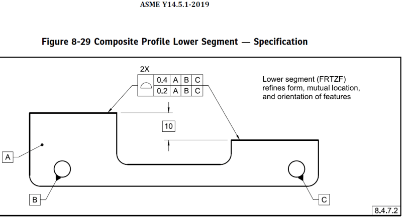
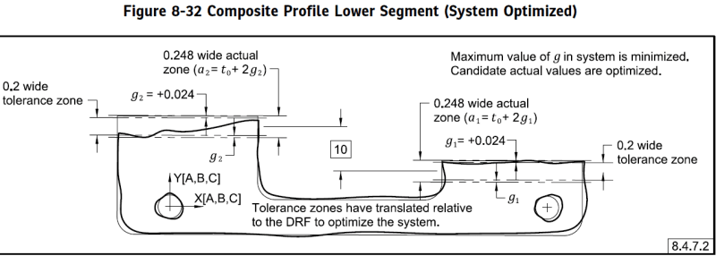
I'm proud to say that we addressed this particular case in Y14.5.1-2019. I included an example in the profile section, that has a composite profile tolerance with a datum feature configuration identical to the OP example. Here are the relevant figures, that show the drawing spec and the final optimized system:
51_Fig_8-29_ljwscc.png


51_Fig_8-32_ygtsvf.png


Note that because of the A|B|C sequence, B defines the XY origin and C defines the w rotation of the X axis. The B simulator expands fully, and then the C simulator expands. If the sequence was A|B-C|, then the B and C simulators would expand simultaneously and constrain the X, Y, and w DOF's together. The resulting DRF would be slightly different in this case.


Evan Janeshewski

Axymetrix Quality Engineering Inc.
 
Evan,
I wasn't aware that there are conflicting explanations or interpretations on DOFs constrained by the lower segments of composites, based on Y14.5. The way I always understood it and explained to my co-workers when asked about it, is that for the constraint of any degree of freedom to take place, there are two conditions that need to be met:

1. The "datum feature simulator" (or datum simulator as I would prefer it to be called) is able to stop (or restrict in the MMB case) the translation or rotation of the part in or about the relevant direction axis.

2. the tolerance zone is stationary relative the datum feature simulator (and consequently, relative to the simulated datum).

A simple example is an orientation tolerance, such as parallelism to a single datum. You mate the part with the surface plate the same way you would for a profile of a surface control referencing the same single datum, and the part is immobilized the same way. The difference is that the tolerance zone for parallelism is movable in the normal direction to the datum plane, while for profile it is stationary in location relative to it.

The same applies to the lower segments of a composite profile or position. The part may be fixtured and immobilized by datum feature simulators such as surface plates, inspection blocks, fixed size or expanding pins, for a second segment referencing |A|B|C| exactly the same as for the upper segment. But unlike for the upper segment, the tolerance zone (or group of zones) is not stationary relative to the established DRF - It can translate (but not rotate). So even if the secondary datum reference in the second segment does not constrain any degree of freedom (because the second condition mentioned above is not met), it is still needed to establish the required datum reference frame.
 
I am apparently really far out of my depth, I cannot visualize (and the example axym provided (fig 8-82) is not helping) how to interpret a composite tolerance that repeats all datums in order with simply a tighter acceptable range. Why does the 0.248 actual not violate the second segment tolerance (aka what did the 0.4 tolerance accomplish in the first place?)?
 
BiPolarMoment,
What that figure shows is that there are two 0.2 wide tolerance zones, associated with the second segment, basically oriented to the DRF and spaced apart by basic 10. These two can float in location, though. They are called the FRTZF. But, the two surfaces shall also fit within the first segment's 0.4 tolerance zones - the PLTZF, which are not shown on that figure, and they cannot float relative to DRF. They are basically oriented AND located to the DRF, and also spaced apart by basic distance 10. From looking at the figure it looks like it shows a non-conforming feature and the 0.248 actual zone does violate the second segment. Looks like the left side surface can't fit within the 0.2 tolerance zone, despite the "optimization" attempt (done by letting the FRTZF float).
 
It would be easier if the committee had simply gone with the Voelcker method and explicitly assigned in each datum reference exactly what components of the 6 degrees of freedom they controlled relative to the datum reference frame rather than requiring the user to figure it out from the convention/context. If it did, the top line would include the X,Y,Z, and u,v,w components and then the lower one would have only the u, v, and w components. If one wanted to float or tighten a particular direction then that degree of freedom would be explicit instead of puzzling it out from context.
 
Burunduk,

Your interpretation of FRTZF's is exactly what I eventually landed on after studying the standard for a long time - the zone framework acts differently (it translates relative to the DRF). But I've found that this interpretation is probably in the minority (even in the Y14.5 committee itself). A lot of people have arrived at a different interpretation that is similar to what greenimi described - that the lower segment datum features act differently and only constrain rotational DOF's. We can find pieces of evidence in the standard to support both interpretations (and probably more for the second one, such as the "certain repeated datum feature references may not constrain any degrees of freedom" which was added in 2009. But it turns out, as you have determined, that if we test both interpretations on actual examples (including 10-43 and 10-44) then only the "zone framework translates relative to the DRF" interpretation is workable.

Your response to BiPolarMoment's question nailed it as well. My figure from Y14.5.1-2019 only shows the FRTZF and not the PLTZF, and the feature is nonconforming.

Evan Janeshewski

Axymetrix Quality Engineering Inc.
 
Evan,
I don't consider specifications such as "certain repeated datum feature references may not constrain any degrees of freedom" as necessarily indicating a wrong interpretation. I take this to mean that one of the conditions is not met by the tolerance zone and the datum feature simulator: either the datum feature simulator is unable to constrain any degrees of freedom that weren't already constrained by preceding datum references due to geometry, or the tolerance zone is allowed to translate relative to the datum feature simulator. But, it doesn't mean that the datum references "do nothing", as they are necessary for the establishment of a datum reference frame that leads to a certain end result. Such as in the OP's example, without the secondary datum hole B the tertiary datum hole C would: 1. Obviously not act as a tertiary datum reference 2. Not be able to constrain the last rotational DOF.
 
Burunduk,

You definitely got the right idea from the statements in 14.5. A lot of people took the "may not constrain any degrees of freedom" purely in terms of the datum features and not in terms of the tolerance zones.

BiPolarMoment,

Here is a marked up version of Figure 8-32 that has the upper segment tolerance zones (PLTZF) drawn in. I decided not to include the PLTZF in the published version, because the figure has so much going on already.

51_Figure_8-32_with_PLTZF_mbhxar.png


This shows what Burunduk described. The 0.4 mm upper segment zones (PLTZF) are centered on the true profile, they have not translated. The 0.2 lower segment zones (FRTZF) have translated downward to optimize the actual value. The little red arrow above the 10 mm basic dimension represents how far they translated.

In this example, both the 0.4 upper segment tolerance and the 0.2 lower segment tolerance are nonconforming.

Evan Janeshewski

Axymetrix Quality Engineering Inc.
 
Status
Not open for further replies.

Part and Inventory Search

Sponsor