Continue to Site

Eng-Tips is the largest engineering community on the Internet

Intelligent Work Forums for Engineering Professionals

  • Congratulations waross on being selected by the Eng-Tips community for having the most helpful posts in the forums last week. Way to Go!

Concentrated Load on continuous one way slab to supporting beams 4

Status
Not open for further replies.

wrxsti

Structural
Sep 18, 2020
196
hello i am trying to analyze concentrated load on decking to beam force transfer
in particular concentrated load directly over beam

in a previous post someone referred to image below
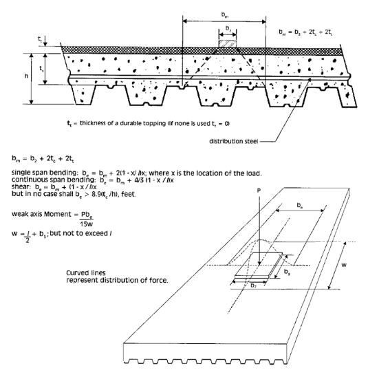
Untitled3_001_jxjkeo.jpg


for distribution of concentrated loads for deck slab design


Is it plausible to use the same for force distribution on the supporting beams?

Instead of image below
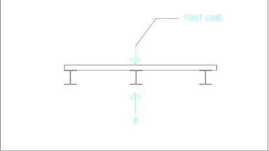
Untitled3_001_fctsez.jpg


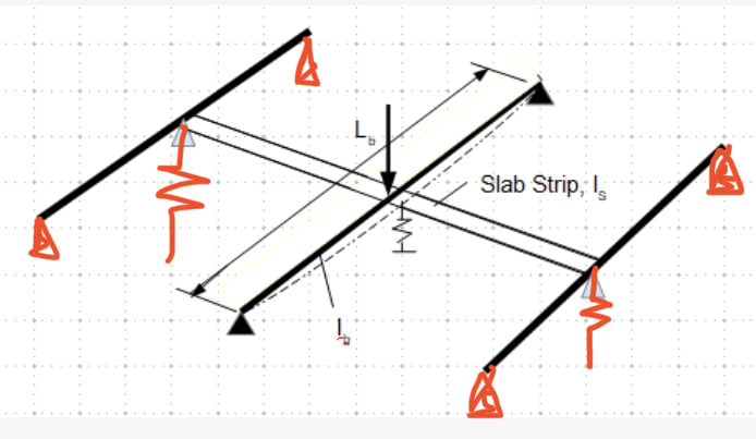
Perhaps this could be used (image below)
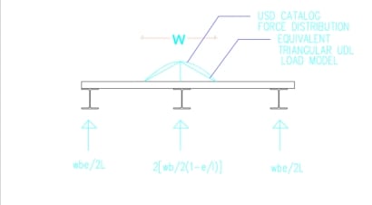
Untitled3_001_tfjo1c.jpg


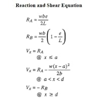
Reference for reaction calcs image below
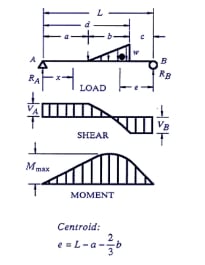
Untitled3_001_jnahbt.jpg

Untitled3_001_sgt9f5.jpg


Also could you refer to further calculation to incorporate the stiffness of the slab into spreading to adjacent supporting beams
in the scenario of concentrated load directly on top of the beam?
 
Replies continue below

Recommended for you

for sure BA the 14 66 14 only represents the point load at the center of the beam
 
how would one find the stiffness of a beam at a particular point given multiple loadings?

i know super position would work for deflection but what is the procedure for stiffness
 
Pay attention to BA's comment. Somehow I started assume the concentrate load is on the midspan of the beam, thus, the deflection is, Δ = PL[sup]3[/sup]/48EI, and K = 1/Δ. If it is located somewhere else on the beam, then you need to calculate the deflection, and the K will change. I hope you get the concept, and understand all the comments/call for cautions, rather than just working out for this particular case.
 
Wouldn’t this be a more realistic model, which I suspect will dramatically affect results..?

E01B9E71-257C-4273-AC28-C243C6F1F2F6_lqytpl.jpg


Also, would the slab not have to deform excessively to get the extent of sharing you’re looking for? As noted above, I’m not sure I’d be entirely comfortable looking for this degree of load share without shear studs. It would make a very interesting thesis!

How far out are you if you take the simple approach of load applied to one beam only?
 
Yes, K = P/Δ. But when calculating member/support stiffness, we apply an unit force, that is P = 1 to get the corresponding deflection. Don't confuse this unit force with the actual applied force, the applied force is used on the model after you have provided the stiffness parameter, "K". Sorry, if I have confused you.

 
IRE,

You are correct. It is more accurate to add all members that will be influenced by the concentrate load. But then you'll have to rely on structural software to get solutions.

Without shear studs, the slab is non-composite, but with the reinforcing steel, it still have flexural capacity, albeit small. I don't want to get too deep into theory of composite slab, but it can be simply put as: a) composite action will affect the stiffness of the beam significantly; and b) as the slab is reinforced, composite action has little effect on the stiffness of the slab in direction transverse to the beam. Correct me, if you feel otherwise.
 
I agree with your rationale on the shear studs.

I think however including pin supports at midspan of the edge beams in the model will naturally take load incorrectly away from the mid beam.

I’d still like to know how far out we are if we go with a simple PL/4 on the mid beam?
 
Yes. I agree with your thought, that we can assume the slab strip is supported by 3 springs.
 
IRE THANKS!


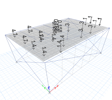
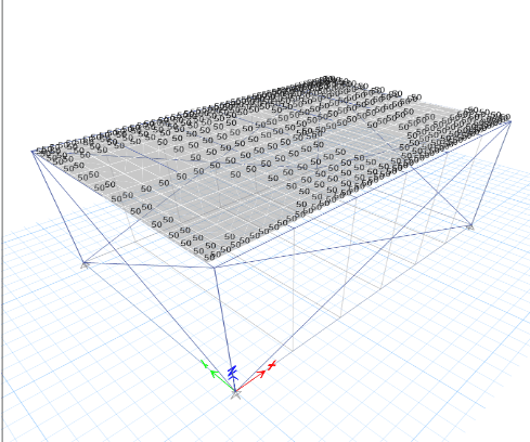
here is an illustration of what im getting at

DL + these below
Untitled3_001_eumarn.png

Untitled3_001_zgaimz.png


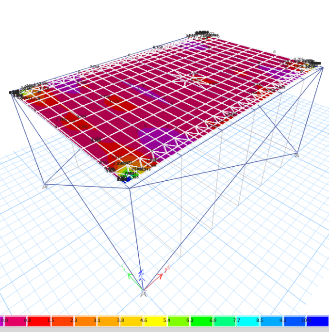
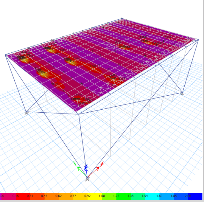
MODEL WITH 4" THICK SLAB DISTRIBUTION FROM STIFFNESS
BM DIAGRAM FOR SLAB ( SCALE 0 - 10 KIPFT )
Untitled10_001_piymot.png


BM DIAGRAM FOR BEAMS
Untitled10_001_q4s9st.png


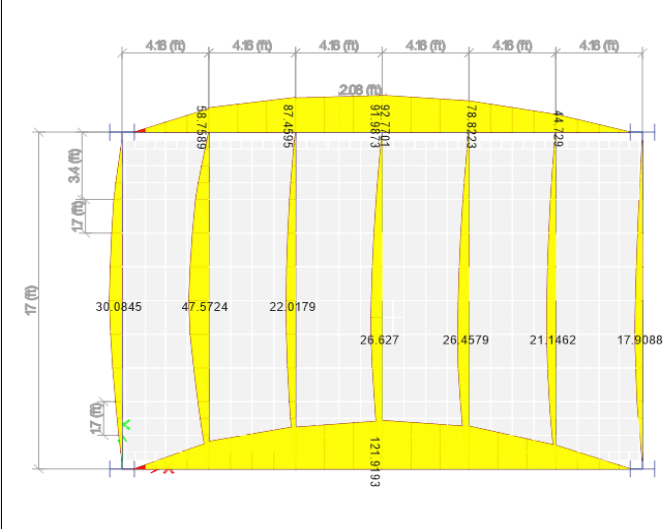
MODEL WITH 4" THICK SLAB NO DISTRIBUTION
BM DIAGRAM FOR SLAB ( SCALE 0 - 2 KIPFT )
Untitled10_001_piymot.png


BM DIAGRAM FOR BEAMS
Untitled10_001_sdq7yd.png


The capacity for the secondary beams = 40kipft
with stiffness slab model second beam from left stays below 40
albeit the model is generating some high moments in the slab at the corner

second model has lower moments in slab
but the second beam from the left is over 40

was hoping distribution would stop this
 
corrected
bm for slab for 2nd model below

Untitled10_001_rcq2wu.png
 
how do you get the stiffness at a point with different loading scenarios?
Stiffness for a point load at the center is 48EI/L^3. If another point load added at center stiffness remains same.
Deflection can be added for superposition but what about stiffness is stiffness increasing at a point the
more loads added?
 
jsmith,

No. As stiffness is 1/Δ, which is the inverse of deflection induced by an unit load at a particular point on the beam. If another concentrate load is added at another location, you need to calculate the two cases separately, then superpose the results.
 
If your slab cracks, are you still guaranteed adequate distribution?

Can you just strengthen the beam and sleep easy??
 
@retired13
taking your model where the stiffness was used but with only one point load on the center of the supporting beam
causing stiffness to be 48EI/L^3
if before this load was introduced another point load was existing other than center causing an deflection before the
center point load.
what procedure could be taken to modify the stiffness in the model to represent that?
 
And all of these questions you're having are the exact reason most of us would just reinforce the beam in question for 100% of the load and be done with it.

How many hours have you spent trying to justify this? a day? two?

So you've now spent $1500 in fees to save them probably $1500 in reinforcing. Just reinforce the beam in question for the full load and be done with it.
 
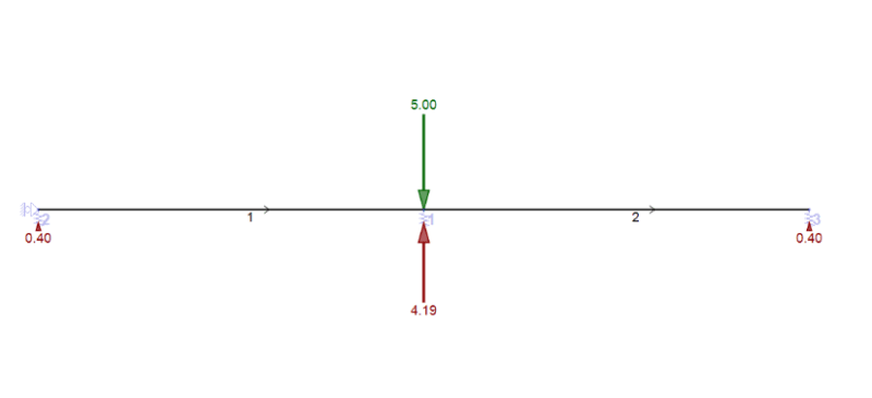
btw the model for 0.25 stiffness modifier for the slab with stiffness 48EI/L3 for 3 supporting beams
in the event of midspan
That is slab section taken as 12inches wide ( 4inch support + 2 slab thickness ) and 4 inch thick
E value modified by 0.25 to simulate 0.25 stiffness modifier as suggested by ACI for crack section

Yield these results
Untitled10_001_nuzzlt.png


So the load distribution is 8 84 8
total reduction of 16pc @ MID SPAN OF BEAMS
for scenario

load distribution would reduce moving between midspan and either support
 
There is no question that the slab can play a role in load sharing when a point load occurs directly over a beam. It is simply not the kind of action that engineers like to rely on. In the life of the building, loads can change in magnitude as can their position on the floor.

Having said that, I am not clear on the reason for selecting 12 inches as the width of slab chosen. If load sharing is to be considered, it seems to me that the effective width of slab is much more than 12", perhaps more like 36", 48" or even more as the steel beam will easily spread the point load over a larger width of slab. And if steel deck is composite and continuous, the moment of inertia of the slab should include the full section, including projections below the 4" slab.

If the magnitude and position of all suspended loads was known with 100% certainty, I would agree with this procedure but, unfortunately, this just isn't the case.

BA
 
Status
Not open for further replies.

Part and Inventory Search

Sponsor