Continue to Site

Eng-Tips is the largest engineering community on the Internet

Intelligent Work Forums for Engineering Professionals

  • Congratulations SSS148 on being selected by the Eng-Tips community for having the most helpful posts in the forums last week. Way to Go!

Concrete Column with Embed Plates

Status
Not open for further replies.

Guastavino

Structural
Jan 29, 2014
381
Document1_fmvczi.jpg


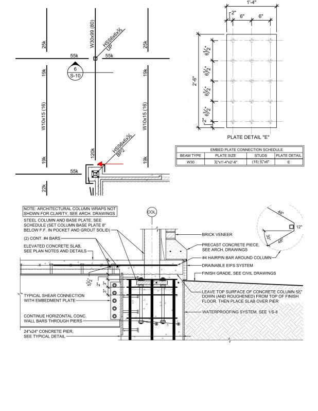
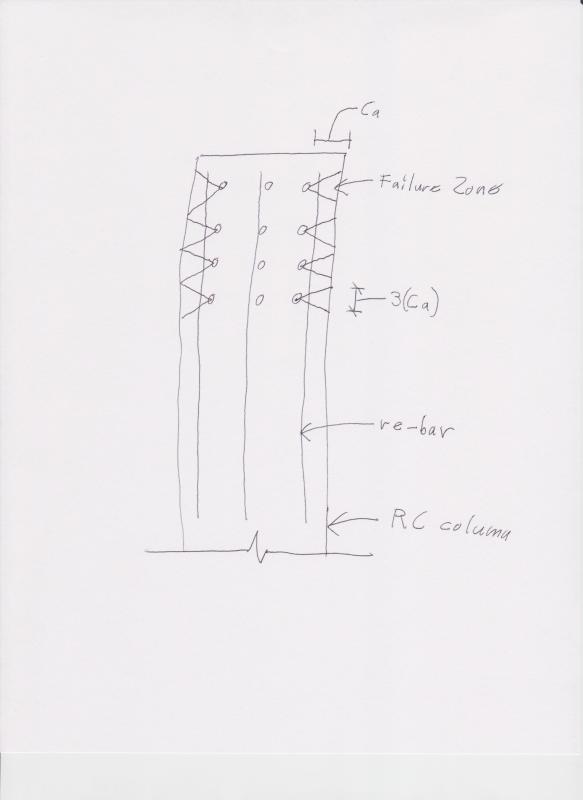
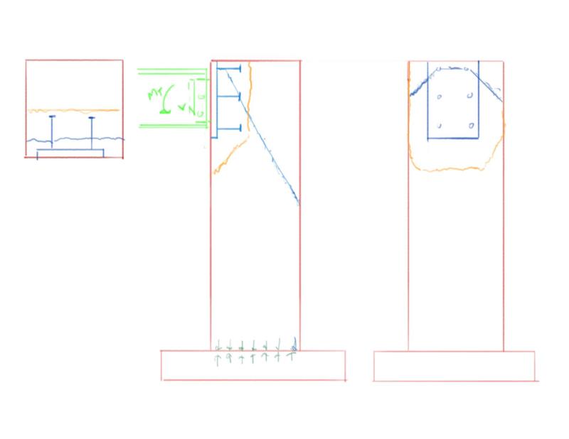
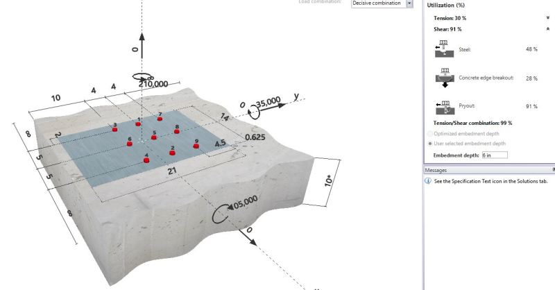
So I've been studying ACI 318-08 App D all day on this particular situation. No examples to be found as I search and search for a concrete column with embed plates. As I understand I need to check Vcbg, but I get to multiply by 2 (Per D6.2.1(c)) since the only load is the 120k Shear load (LRFD level) is parallel to the nearest edge. That yields only about 30ish kips of allowable load for quite a robust embed plate. Now, I can of course use the D6.2.9 anchor reinforcement, but I can't really fathom what the failure plane would be for a column embed like this, thus I don't know what rebar to develop.

To me Vcbg doesn't make sense for a column like this. Pryout check makes sense (but even then stirrups help prevent that), and when I check that I get 127.5 kips of capacity.

Anyone encountered this before and have thoughts?
 
Replies continue below

Recommended for you

The way I see it is the hairpin (hopefully) will try to take on the load......but 1 #4 isn't going cover this kind of shear load. The next thing to try is to see if the stirrups and vertical reinforcement in that pier can handle the job. I've typically used a strut and tie model to get the shear to the vertical reinforcement (from the anchors; and the stirrups to anchor the tensile zone created in part of the pier).

The plate doesn't really do a lot for you in that situation. (Except for the uplift load.)
 
Thanks but I'm not at all concerned about the column plate. Concerned about the W30 beam shear load into the concrete column below.
 
Thanks but I'm not at all concerned about the column plate. Concerned about the W30 beam shear load into the concrete column below.

Ok, that helps. I thought we were talking about the shear load from the HSS.

For that stud group, I don't know if the spacing is large enough to preclude a group failure, but on a stud by stud basis, to quote sect D.6.2.1 (which you mentioned):

"For shear force parallel to an edge, Vcb or Vcbg
shall be permitted to be twice the value of the shear
force determined from Eq. (D-30) or (D-31), respectively,
with the shear force assumed to act perpendicular
to the edge and with ψed,V taken equal to 1.0.
"

Essentially twice the load cap. as if it was acting perpendicular to the edge. If the spacing of the studs is 3 times the edge distance.....group effects would not be involved.
 
Thanks WARose...I get the twice the load cap...my question is what would the failure plane be so that I can determine if I meet 6.2.9, or I'll try to add rebar to prevent a shear plane from opening. I just can't figure out a failure mechanism for Vcbg to know what/where to put rebar.

As an aside, I'm not convinced that Vcbg calculation would accurately predict anything for this application...but it is the code!
 
As far as the embed plate goes....it's not embedded deep enough to consider as a alternative mechanism for failure. I think one thing that would trip it up right off the bat would be the bearing on that edge being too excessive.

As far as the re-bar goes.....you could treat it like shear reinforcing (in Appendix D): anchor the re-bar in the failure zone and develop it beyond that. The interesting question with that would be the development length to use......compression or tension? I would think compression....but not sure.
 
>>>Anyone encountered this before and have thoughts?<<<

In the days prior to Appendix D I’ve seen sections of beefy W14’s & W12’s cast into the concrete with just the face exposed. The beams and a stiffener seat were both field welded to it. I don't know if that would overly interfere with your column reinforcing in your situation but it’s just another potential avenue to explore.
 
Yea, my problem is that I cant figure out what the failure zone would be.

I may just drop the steel column down and connect the beam to the column, then just fill the top of the pier/corner retaining wall with concrete and be done with it. Makes the concrete placement at the top more difficult, but is a better connection I would think
 
my question is what would the failure plane be so that I can determine if I meet 6.2.9,...

To me, it would look something like Fig. RD.6.2.1(c) or (d) [second pic]. I would think if you have anchorage in those (shaded) zones you would be ok.
 
Thanks WArose, so how far down the column would the bottom of that go? The only free edges are parallel to the load, and the studs are in the column core bounded by ties and #8 bars (Concrete column has 8 #8 bars). Therefore, the concrete would in a sense have to spall off somehow. I think it's ironic that RD.6.2.1(c) doesn't show a failure plane. The 2x calculation seems to be like the 1.9 in the ASCE 7 wind loads for rooftop equipment. I.E>, it's an acknowledgement that we don't really know, but this seems like a reasonable approach.
 
Thanks WArose, so how far down the column would the bottom of that go?

I would think (from the centerline of the anchor) 1.5 * the edge distance.
 
I plugged your design into Hilti Profis and got a failure big-time. Unity was about 5.9.

This assumes a 2 1/2" eccentricity from the 120 kip vertical shear load from the bolts back to the column face and assuming f'c = 5000 psi for the concrete.

The distance from the top headed studs to that construction joint was included - only perhaps 3" or less?


Check out Eng-Tips Forum's Policies here:
faq731-376
 
JAE, It’s actually about 6” as I would likely abut some hairpins in to lock that slab down.

Ultimately there is no way to make numbers figure for the column without 6.2.9 anchor reinforcing. The question is where is the failure plane. I don’t know...see below for my thoughts but again I think app d falls short on this

BBFC1F3F-E2AE-4624-89F2-B1380CC801A4_jpss1j.png
 
With that magnitude of shear load I'd be inclined to extend the beam OVER the concrete column and have the column above frame into the top of the beam...with stiffners as required.


Check out Eng-Tips Forum's Policies here:
faq731-376
 
To me, it would look something more like this (by code):

1.17.17_001_jq5tax.jpg


Obviously, you'd be limited by how much the bar develops in each "failure zone". The force in the bar would be cumulative, and you would develop it fully once the studs end. Capacity would be X number of studs * the afore mentioned capacity.

I like JAE's latest suggestion about putting the beam over the column.
 
I'd think the shear breakout "failure" line would extend to the rear face of the column and the remaining chunk is resisted from falling by the foundation so in this instance this type of anchor failure would not produce a structural failure per-se but an unsightly crack thru the column depth. (blue line)

Tension breakout and shear pryout would be likely failure mechanism which I would think would create a failure plane that returns to the same face of the column as the emebed (yellow line). There is likely going to be some incidental moment created by the construction tolerances allowed. I would make sure to spec a slotted connection for at least one end of this beam as well, got bit on a job with an embed where beam was installed in summer building was still open in the winter and the shrinkage failed the embed.

1_xf74jy.jpg


Open Source Structural Applications:
 
I'd agree that the failure plane is as per WARose's last post, this is how studs fail close to an edge. In reality the studs failure surface from individual studs are going to overlap for any closer studs at larger edge distances forming one larger breakout zone.

I'd also point out there is a tension on the central row of studs in carrying the eccentricity moment from the simply supported beam. because your beam cleat is central, all of the tension load goes into the central row.

On the assumption of the plate being relatively stiff in plane each row of studs could be assumed to take ~1/3 of the shear, with the outer rows only taking shear, and the central row taking an elastic distribution of tension force (higher tension on top studs, compression at base of the web/fin plate)+ approximately 1/3 of the shear.

As you are no doubt finding the concrete breakout strength won't give you a lot of capacity especially when close to the edge, you might need to justify additional shear stirrups/ties in the column with a strut and tie, or redistirbute studs to have more edge distance to engage more concrete and/or to anchor stirrups past the failure plane which I believe is/was allowed in appendix D.
 
The failure mode that you're looking for here is pryout. I would include an eccentricity off of the face of the column as JAE suggested but, even without that, there is still an eccentricity between the shear at the face of the column and the locations around the failure frustum where the shear is ultimately resisted as some combination of bearing and shear. With infinite edge distances to the sides, that's your classic frustum of concrete behind the plate. With 6" side edge distances and 6" studs, the pryout failure probably starts to take on a character similar to what WARose has proposed. Since your side cover is less than 1.5 h_ef, those local failure are not necessarily precluded. I imagine that your failure is the lesser of the value obtained looking at a local stud blowout and that obtained looking at a whole frustum pryout.

To the issue of scale, I did the embed shown below this morning. Similar proportions, infinite side cover (wall), and lots of eccentricities. 35K capacity; maybe 60K with the misalignment eccentricity removed. The real plate has another row of anchors making the layout symmetrical. Interestingly, capacity is higher with those anchors ignored as the the most demanding local stud failures are not considered. I'm sitting on the fence regarding the validity of the design check but that's a subject or another post of my own.

Your supplementary reinforcing here, for pryout, would be your column ties I think. That said, I'm not sure that we're allowed to use supplementary reinforcement to address pryout.

OP said:
JAE, It’s actually about 6” as I would likely abut some hairpins in to lock that slab down.

I still wouldn't count the slab as part of your breakout concrete. You'd have to move the breakout frustum in the column a fair bit before engaging the slab I suspect.

c03_xrwukg.jpg


I like to debate structural engineering theory -- a lot. If I challenge you on something, know that I'm doing so because I respect your opinion enough to either change it or adopt it.
 
[blue](Agent666)[/blue]

I'd agree that the failure plane is as per WARose's last post, this is how studs fail close to an edge. In reality the studs failure surface from individual studs are going to overlap for any closer studs at larger edge distances forming one larger breakout zone.

Right. My sketch was based on the studs being "far" from each other (to get more capacity). If it's close enough to where the zones overlap....it will get more like Celt83's sketch.

 
I wouldn't agree with Celt83's sketch for shear failure surface, maybe for tension the failure surface would be at the head of the studs. For shear, failure starts at the surface at back of plate/stud weld region like you implied and as shown in many of the figures in ACI code (its just a trapazoidal shape when they overlap but the same fundamental failure surface)
 
Status
Not open for further replies.

Part and Inventory Search

Sponsor