Continue to Site

Eng-Tips is the largest engineering community on the Internet

Intelligent Work Forums for Engineering Professionals

  • Congratulations waross on being selected by the Eng-Tips community for having the most helpful posts in the forums last week. Way to Go!

Constructive Feedback Solicited...

Status
Not open for further replies.

RodRico

Automotive
Apr 25, 2016
508
I just filed a fourth patent addressing fuel injection and charge homogeneity in my engine design, particularly in small versions. Constructive criticism is welcome and is in fact solicited.

This approach injects into a mixing chamber to create a rich charge (stoichiometric in the smallest engine) then injects the charge into the cylinders where it mixes with air to yield the desired equivalence (0.46 max). The mixing chamber averages injector variance, the charge injected into the cylinder is of significant volume which reduces the impact of manufacturing tolerance, and the fact that the injected charge is premixed yields a much better final mix in the combustion chamber. Note the final count of injectors, the configuration of the mixing blades, and the pressure at which the premixed charge is injected into the cylinders are currently undefined and will be determined by CFD.

Note I filed the patent defensively... I don't care if it's patented, I just don't want someone else to patent it and thus prevent me from using it. It used to be that one could simply publish to prevent others from patenting something, but I understand that's not always the case under the America Invents Act. There's a lot of prior art in the approach and that makes me believe it's not patentable, but it does have two-stage injection that I couldn't find in prior art, so I spent the $75 and file a provisional.
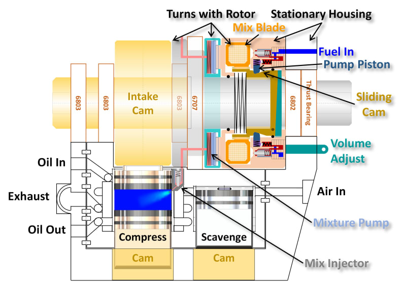
Picture2_v07yhl.jpg
 
Replies continue below

Recommended for you

Seems quite complex and has a number of seals and moving parts?

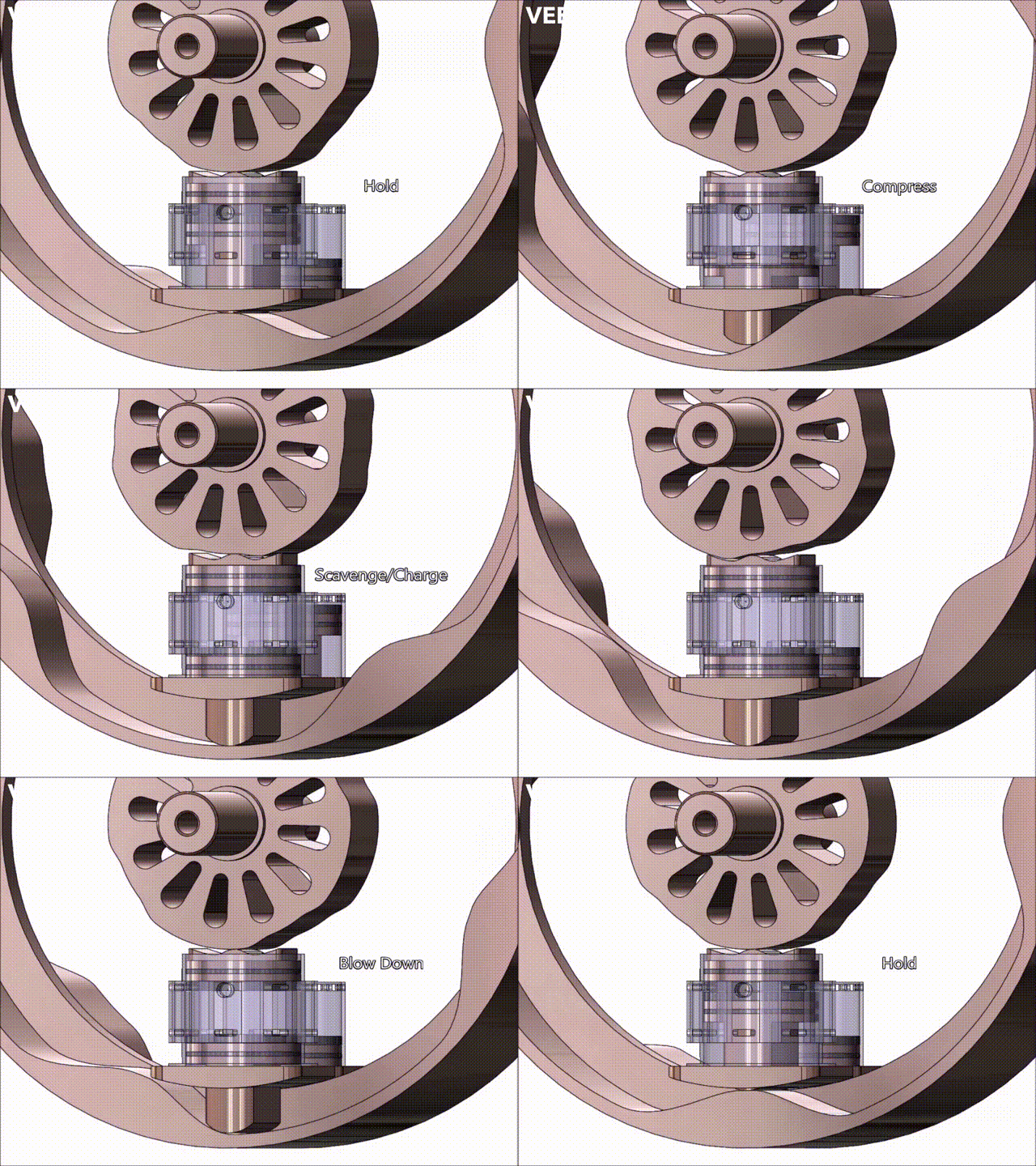
Can't see how this works exactly as there isn't an animation or steps of the phases.

Is this just a design or has it been built?

What do those cylinders do that are moved by the cam?

Basically I can't work out how its supposed to work from one diagram.

Remember - More details = better answers
Also: If you get a response it's polite to respond to it.
 
LittleInch said:
Seems quite complex and has a number of seals and moving parts?
It is a bit complex, but perhaps not as bad as it looks given the internals of the fuel pump and injectors are shown (which isn't common in an engine illustration.

LittleInch said:
Can't see how this works exactly as there isn't an animation or steps of the phases.
Sorry, I thought everyone here was already familiar with the engine concept and was just soliciting comments on the new fuel injection scheme.
Below is a simplified animation showing the cycle, and the attached document describes the design decisions behind the design.

Cycle_Video_tcdurw.gif


LittleInch said:
Is this just a design or has it been built?
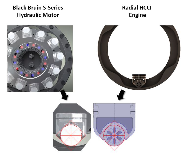
Just a design backed by analysis (not just a cad exercise). I was just recently granted the patent covering the version I plan to build, and have been soliciting criticism to find any issues before proceeding with having key pieces fabricated so I can start experiments. The updated fuel injection system is the result of refinement following concerns people voiced about matching tiny fuel in injectors, for example. Others have urged incorporation of a roller in the cam followers, so I'm investigating putting a single roller on the cam followers similar to that used in the Bosch Rexroth hydraulic engine at
Hopefully the above gives you what you need to better understand the engine. Let me know if you need more.
 
enginesrus said:
It will be nice when its up and running.

I'm using social media for the peer reviews I used to have with my team, and I haven't been able to go public with each design iteration until the applicable patents are granted.
I did one round of review when the first patent issued, incorporated a number of revisions based on discussion and the deeper understanding that resulted, then filed the second patent.
Since the second patent is now approved, I can share the results of the refinement from the first round to begin what is hopefully the final round.

I've already filed a third patent over the mixing chamber which resulted from discussion of unit-to-unit variance in the injectors and wall wetting in small bore cylinders with a professor.
I currently working to incorporate a roller on the end of the piston based on widespread distrust of the sliding cam follower. I'm simultaneously evaluating two options:
1) A single large roller on a pin as is common in roller lifters. Nice and simple, but it restricts the width of the roller which ripples into higher stress on the cam and roller.
2) A single large roller wrapped in a half journal bearing (shown below). Nice and simple and allows the widest possible roller, but may be risky (still evaluating).

Though I thought the effort would go faster when I started, I've since learned it often takes a team of professionals five years to design a new engine, so I don't think my six year solo effort is unusual.
I'm just happy the engine has evolved to a much better configuration as a result of all the discussion and peer review from a handful of folks willing to take the time to comment constructively.
Once I have incorporated the roller and run it through FEA, all that's left (I think) is detailed design of the mix injection system and CFD of the result.
I hope to be able to start critical experiments by the end of the year. Based on past experience, that's probably unrealistic, however.
All I can do is keep slogging through.

Capture_zom1gq.jpg
 
Do you need something to make that journal bearing spin and will it be bad if it doesn't?

What I see it the external rotor and journal act on the round bearing with exactly the same moment arm, how does this roller bearing 'decide' to spin instead of slide?
 
moon161 said:
Do you need something to make that journal bearing spin and will it be bad if it doesn't?
What I see it the external rotor and journal act on the round bearing with exactly the same moment arm, how does this roller bearing 'decide' to spin instead of slide?

Good question.

There's unavoidably oil on the track, and it piles up on the leading edge of the roller (at the lower right) where it meets the track.
There will also be oil on the trailing edge (at the upper left) of the roller where it enters the bearing, but much less due to the geometry and nature of the interface
(the only oil on the trailing side of the roller is that which adheres to the it due to viscosity, and the barrier to oil entry into the bearing interface is smaller).
The roller turns because there is more force on the leading edge where it meets the track than on the trailing edge where it enters the bearing.

I imagine the unconventionally sharp edge on the bearing where it meets the roller in the hydraulic motor shears off excess oil that accumulates there.
With less oil piling up at the entry to the bearing, the amount of oil that must pile up on the leading side of the roller before it rotates is reduced.

It will be interesting to see the CFD results (assuming I can get it to model this case).

 
moon161 said:
Do you need something to make that journal bearing spin and will it be bad if it doesn't?

What I see it the external rotor and journal act on the round bearing with exactly the same moment arm, how does this roller bearing 'decide' to spin instead of slide?
Much thinner oil film at the rolling (Elastohydrodynamic) interface than at the journal bearing surface which should always be in the hydrodynamic regime.

je suis charlie
 
Solidworks Flow Simulation (CFD) allows multiple rotating reference frames, so I should be able to model the cam interface in a limited fashion. I'll post results once I have them (assuming I can get it to work).
 
I will be impressed if this engine will last 100 hours. What will the hardness be of the parts in contact with the cam as well as the cam? And what for lube?
 
enginesrus said:
I will be impressed if this engine will last 100 hours

I'll be overjoyed to see it run as expected for 10 hours as a first step! Seriously, though, durability worries me too.
If I find I must make the cams less demanding, I'll run it at 5,252 RPM rather than 2,626 and reduce cycles per revolution from four to two.
If I can't attain durability, I'll admit the project is a quasi-failure (quasi because getting full-time HCCI/LTC working over temperature will be an accomplishment in and of itself).


enginesrus said:
What will the hardness be of the parts in contact with the cam as well as the cam? And what for lube?

I designed for Maraging 350 but am now evaluating Vibenite 150 as well (450 kpsi yield, HRC 64). Reducing cycles from four to two while doubling RPM as mentioned above may allow use of H-13.

Capture_zfuzkh.jpg


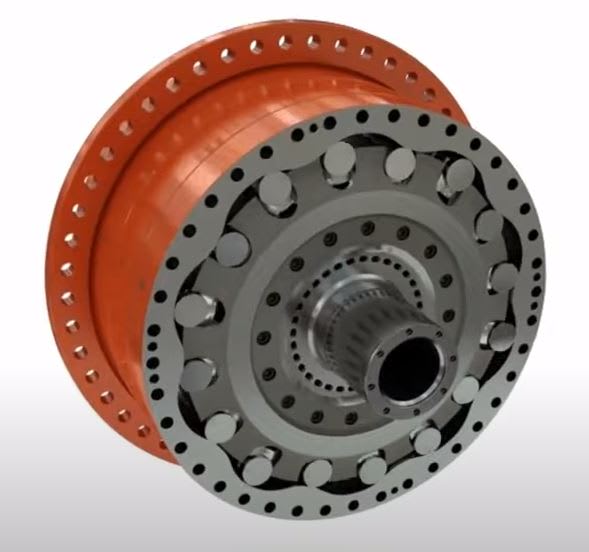
P.S. My level of hope increased markedly after discovering the Bosch Rexroth Hägglunds CB 400-240 hydraulic motor shown below. It has four rotors, each completing 10 cycles per revolution, producing 57,000 lb-ft of torque (14,250 per rotor) at 125 RPM. Though mine is running faster (4 cycles per revolution at 2626 RPM vs 10 cycles per revolution at 125 RPM), a 27.2 HP (20.2 kW) version of my engine targeting a range extender application (Class-2 charger) produces only 54.4 lb-ft of torque. See a video of the Hägglunds motor at and the specifications on page 11 of the document at
Capture_uzoshi.jpg
 
Bear in mind that the hydraulic motor operates with its internals submerged in oil.

je suis charlie
 
gruntguru said:
Bear in mind that the hydraulic motor operates with its internals submerged in oil.
Granted, but most of that oil does nothing but create loss. As you well know, the only oil that matters is the thin film between the follower and the cam.
I'm still encouraged by a reputable company driving so much torque through cams with such high mechanical efficiency.
 
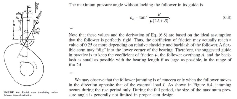
Someone pointed me to the excellent "Cam Design Handbook" by Harold A. Rothbart. I found the 2004 edition online.
Chapter 6, "Elements of Came Profile Geometry" addresses pressure angle thus:

Rothbart_Pressure_Angle_z04bjy.jpg


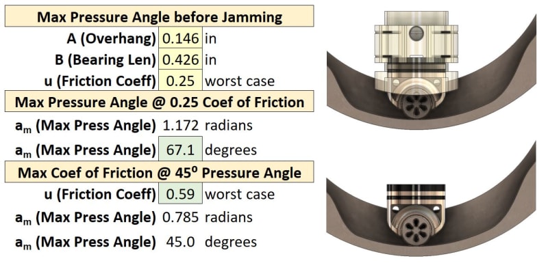
Below is my cam with the new rolling follower piston (with and without the cylinder liner) and the calculation of maximum pressure angle.
Note that B = 2.9A (exceeding the 2A recommendation), the piston to cylinder clearance (backlash) will be 0.001 inches, and all components are made of Maraging 350 steel.

Cams_and_Calcs_q3hwem.jpg


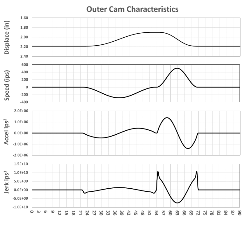
My current cam design, shown below, has 30 degree pressure angle on rise (compression) and 45 degree pressure angle on fall (expansion).
Note this is a new profile constructed using a cycloid waveform for acceleration followed by derivation of speed and displacement.
The new method, recommended by a reviewer in another forum, has smooth acceleration and finite jerk.

Cam_Profile_gpyixq.png


It turns out I "stumbled" into the proper cam design in regards pressure angle (shallow on rise, steep on fall) by assessing mechanical efficiency (when the cam is driving, pressure angle should be as shallow as possible, but when the follower is driving, it should be as steep as possible) and stress (overhang should be small and the support length long). It is rewarding to see those mechanical analyses yielded a design that complies with accepted cam design practice. I also "stumbled" into a bad method for calculating the profile that resulted in excessive jerk, however, so I'm very grateful to the peer who spotted the error and recommended a course of action that resulted in a better design.

With textbook references substantiating the cam design, I'm done questioning its validity.
I'm now off to confirm peak loading under dynamic conditions is within the margin of safety.
 
Status
Not open for further replies.

Part and Inventory Search

Sponsor