sticksandtriangles
Structural
- Apr 7, 2015
- 494
The recent concrete wall questions in this forum have got me thinking a lot about concrete shear wall design.
A few questions for the group:
1. How does designing wall elements as individual pier elements verse designing a whole section affect DCR ratios and overall design capacities?
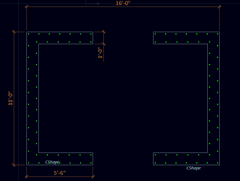
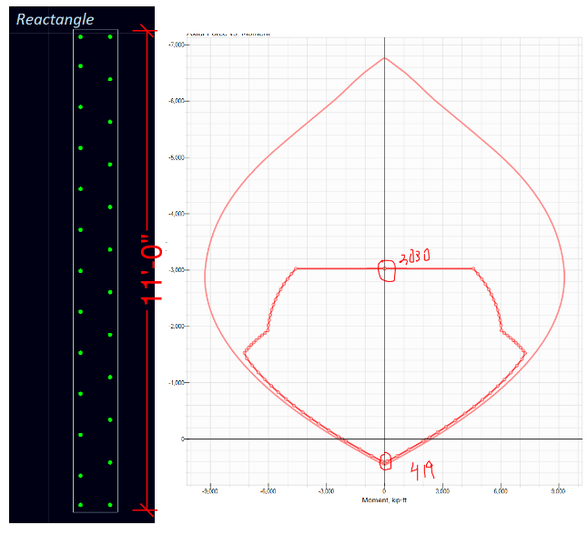
I ran an example below, 12" thick concrete walls with #5 @ 12"oc vertically, in a sort of coupled C shape shown below, analysis about the strong axis of this shape (left to right).
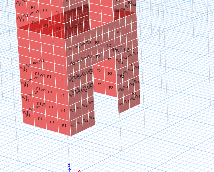
Etabs model has two different ways of labelling piers:
1a. Individual Piers (F1 and F2 are the flanges, W1-W4 are the separate webs)
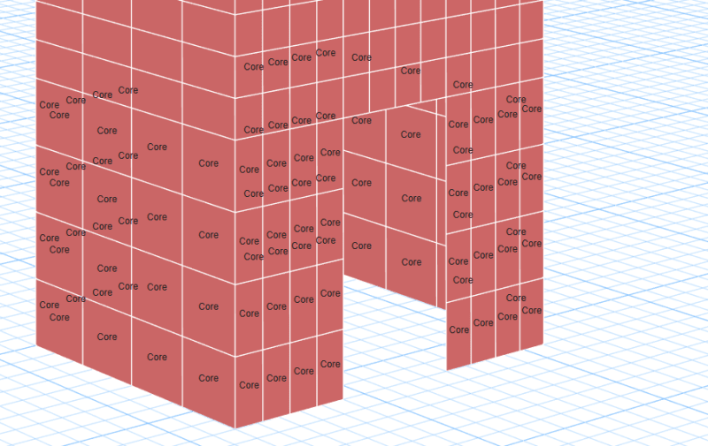
1b. Whole section
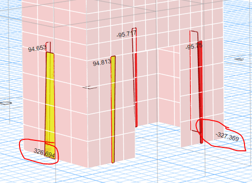
I started by just looking at flexural demands on the core with fictitious lateral loading (no vertical loads applied).
In option 1a. the resulting force couple in F1 and F2 (flange pier labelling) is ~ 327 kips.
Beginning with the tension wall pier, I get a capacity of 419 kips, DCR of ~0.8. The compression wall pier, I get a capacity of 3030kips, DCR ~0.11
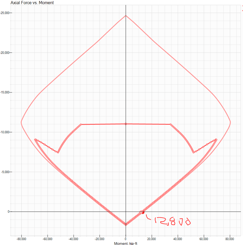
In option 1b. I get a flexural capacity of about 12,800kip*ft, with a demand of 6600 kip*ft for the same loading. This DCR is ~0.52.
You can see the discrepancy here, the person designing their wall based on individual piers has a DCR of 0.8 vs a person designing their walls as a whole core has a DCR of 0.52. Is one the "more correct" way of analyzing the wall?
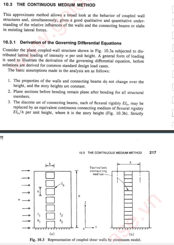
2. At some point, the spandrel beam connection these (2) C shapes is not strong/stiff enough to make these corewalls act compositely, correct?
That would make analyzing these walls via option 1b incorrect? Is there any guidance on when the spandrel beam is strong/stiff enough to consider the whole wall assembly acting compositely? I am also out in seismic land and this could have some big impacts on wanting plastic hinging to be flexural and not failing in shear before flexural yielding occurs.
The nominal flexural capacity of the whole coupled shape is the 14,200 kip*ft, vs the (2) individual C nominal flexural capacity of 4450 kip*ft, factor of about 3.2.
Thanks!
S&T
A few questions for the group:
1. How does designing wall elements as individual pier elements verse designing a whole section affect DCR ratios and overall design capacities?
I ran an example below, 12" thick concrete walls with #5 @ 12"oc vertically, in a sort of coupled C shape shown below, analysis about the strong axis of this shape (left to right).
Etabs model has two different ways of labelling piers:
1a. Individual Piers (F1 and F2 are the flanges, W1-W4 are the separate webs)
1b. Whole section
I started by just looking at flexural demands on the core with fictitious lateral loading (no vertical loads applied).
In option 1a. the resulting force couple in F1 and F2 (flange pier labelling) is ~ 327 kips.
Beginning with the tension wall pier, I get a capacity of 419 kips, DCR of ~0.8. The compression wall pier, I get a capacity of 3030kips, DCR ~0.11
In option 1b. I get a flexural capacity of about 12,800kip*ft, with a demand of 6600 kip*ft for the same loading. This DCR is ~0.52.
You can see the discrepancy here, the person designing their wall based on individual piers has a DCR of 0.8 vs a person designing their walls as a whole core has a DCR of 0.52. Is one the "more correct" way of analyzing the wall?
2. At some point, the spandrel beam connection these (2) C shapes is not strong/stiff enough to make these corewalls act compositely, correct?
That would make analyzing these walls via option 1b incorrect? Is there any guidance on when the spandrel beam is strong/stiff enough to consider the whole wall assembly acting compositely? I am also out in seismic land and this could have some big impacts on wanting plastic hinging to be flexural and not failing in shear before flexural yielding occurs.
The nominal flexural capacity of the whole coupled shape is the 14,200 kip*ft, vs the (2) individual C nominal flexural capacity of 4450 kip*ft, factor of about 3.2.
Thanks!
S&T
![[upsidedown]](/data/assets/smilies/upsidedown.gif "[upsidedown] [upsidedown]")
![[bigsmile]](/data/assets/smilies/bigsmile.gif "[bigsmile] [bigsmile]")