Continue to Site

Eng-Tips is the largest engineering community on the Internet

Intelligent Work Forums for Engineering Professionals

  • Congratulations SDETERS on being selected by the Eng-Tips community for having the most helpful posts in the forums last week. Way to Go!

Coupled Concrete Shear Wall Design Questions

Status
Not open for further replies.

sticksandtriangles

Structural
Apr 7, 2015
494
The recent concrete wall questions in this forum have got me thinking a lot about concrete shear wall design.

A few questions for the group:

1. How does designing wall elements as individual pier elements verse designing a whole section affect DCR ratios and overall design capacities?

I ran an example below, 12" thick concrete walls with #5 @ 12"oc vertically, in a sort of coupled C shape shown below, analysis about the strong axis of this shape (left to right).
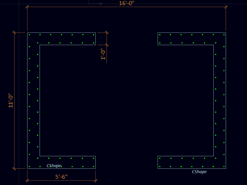
image1_sd87cl.png


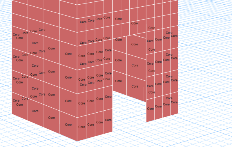
Etabs model has two different ways of labelling piers:

1a. Individual Piers (F1 and F2 are the flanges, W1-W4 are the separate webs)
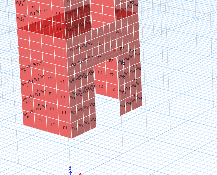
image2_c7yn7t.png


1b. Whole section
core_qxo0rj.png


I started by just looking at flexural demands on the core with fictitious lateral loading (no vertical loads applied).

In option 1a. the resulting force couple in F1 and F2 (flange pier labelling) is ~ 327 kips.
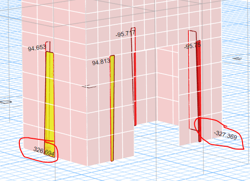
image1_gpzuve.png


Beginning with the tension wall pier, I get a capacity of 419 kips, DCR of ~0.8. The compression wall pier, I get a capacity of 3030kips, DCR ~0.11
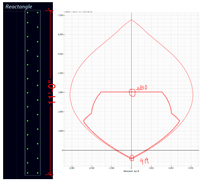
image1_ru7mug.png


In option 1b. I get a flexural capacity of about 12,800kip*ft, with a demand of 6600 kip*ft for the same loading. This DCR is ~0.52.
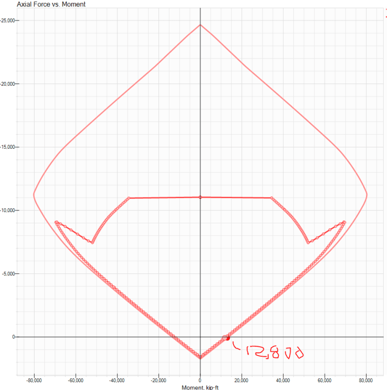
image1_lnirxd.png


You can see the discrepancy here, the person designing their wall based on individual piers has a DCR of 0.8 vs a person designing their walls as a whole core has a DCR of 0.52. Is one the "more correct" way of analyzing the wall?

2. At some point, the spandrel beam connection these (2) C shapes is not strong/stiff enough to make these corewalls act compositely, correct?

That would make analyzing these walls via option 1b incorrect? Is there any guidance on when the spandrel beam is strong/stiff enough to consider the whole wall assembly acting compositely? I am also out in seismic land and this could have some big impacts on wanting plastic hinging to be flexural and not failing in shear before flexural yielding occurs.

The nominal flexural capacity of the whole coupled shape is the 14,200 kip*ft, vs the (2) individual C nominal flexural capacity of 4450 kip*ft, factor of about 3.2.

Thanks!


S&T
 
Replies continue below

Recommended for you

Hi S&T, did you manage to have a quick read of the paper I shared in my recent thread? I contacted the paper to author to ask about how link beams would affect everything. The program assumes a constant strain profile across the section but can be used to calculate the overall capacity of the system not just individual piers (similar to ETABS).

When link beams can't provide 'perfect' coupling (for example, usually over lift doors), such as when you're coupling the stair and lift core over a lobby, the link beam stiffness will affect the distribution of forces. In these cases, you could do up a simple frame model with a cracked linking element to get the final axial, shear and bending loads on the stair and lift core separately.

I assume to determine how perfect your coupling is would need a sensitivity analysis to show when a link beam is stiff enough to result in less than 5% change in pier forces?

 
S&T said:
How does designing wall elements as individual pier elements verse designing a whole section affect DCR ratios and overall design capacities?

1) In general, as you've posited, I would expect individual pier modelling to produce higher DCR with respect to raw flexural capacity. And I think that this is one of the appealing aspect of that method for practicing engineers: at least you've got more moment capacity than you need... yay! There are some problems when it comes to the more nuanced aspect of core wall design however:

a) In a model that does not pay homage to cracking induced redistribution of actions within a single core, you may get reserve capacity overall but a higher than expected demand in some hotspot areas. This might matter for, say, wall buckling tendency in the part of the core in aggregate flexural compression.

b) For seismic design, basing plastic hinge capacities on individual pier modelling may grossly underestimate core flexural over strength, resulting in other members of the structure being under designed.

S&T said:
2. At some point, the spandrel beam connection these (2) C shapes is not strong/stiff enough to make these corewalls act compositely, correct?

Most practical designs will have to acknowledge that we're usually on a continuum between perfectly composite and perfectly non-composite. Very few buildings have stiff enough coupling beams for them to be considered perfectly composite at all levels. It actually tends to be quite a problem when coupling beams are grossly stiffer at some levels than others as you wind up with undesignable coupling beams at the stiff levels and a need to start weaving creative stories about how cracking in those coupling beams will help you to sort that. In my opinion, it's much better to have a uniform distribution of coupling beam stiffness throughout the levels of a building.

At the other extreme, it's actually pretty hard to make a core assembly truly non-composite. In Priestley's tome on displacement based seismic design, they actually postulated methods for using just the slab between wall segments, with no discrete coupling beams, to get the coupling done.

S&T said:
That would make analyzing these walls via option 1b incorrect?

In a strict technical sense, methods 1a & 1b are both incorrect all of the time. But, alas, one has to pick their poison. That, or get into bracketing solutions and partially composite modelling.

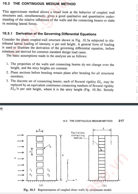
Connoisseurs of shear wall design might enjoy looking into the Continuous Medium Method. Computers killed this elegant method off in a hurry but it still provides a nice conceptual framework for thinking about these things while you're at the pub or trying to sleep.

C01_gxlt8m.jpg


c02_kwkh87.jpg
 
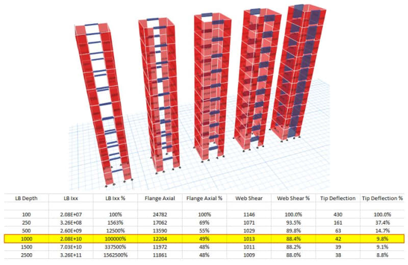
To keep the conversation going, I did up a quick test to demonstrate when I believe you can claim you've achieved 'perfect coupling' through increasing link beam stiffness.

I've tried to stick to your dimensions, S&T, even though they are a few centuries behind the rest of the world [upsidedown]

Obviously a lot of variables go into the stiffness of link beams and how it should be iterated (ref: KootK), but you could run a bunch of sensitivity tests to see how far off perfect coupling you are for real projects.

Few other notes:

- The flange minor axis bending decreased 85% from the 100mm LB to the 2500mm LB.
- Designing each pier as a set of individual walls, the total vertical rebar required reduced by 60% going from the 100mm LB to 1500mm LB.
- This goes to show it's tending towards perfect coupling and the flanges are more utilised as axial governed elements, rather than bending elements.

- The less coupling you have, the more unconservative to design the core as a compound shape.


SW1_pf5eno.jpg
 
Sorry, meant to post to this over the weekend... too much good snow to ski to spend time on an engineering forum [bigsmile]

Trenno said:
did you manage to have a quick read of the paper I shared in my recent thread?

Yep, I read through it, seems like a good piece of software. I would like to get my hands on it and compare it to the software that I showed in the initial screenshots to see how closely they compare. I was a little disappointed to hear that there was not good agreement on the more compound shapes and testing, although it looked like it was within 25% of testing which I would call good enough for engineering purposes.

Let me know if the authors respond to your questions, it would be good to know what they have to say.

KootK said:
In general, as you've posited, I would expect individual pier modelling to produce higher DCR with respect to raw flexural capacity

As I've thought more and more about this, I've come to the same conclusion. Individual piers can't match the same raw flexural capacity of the compound shape (due to all the extra yielding of rebar in the webs that is being neglected in indiv. pier techniques etc.). I feel better about my previous shearwall designs now, always having done indiv. pier modeling design.

Trenno, sorry for the weird units, maybe one day we will make the switch.
What was your story height out of curiosity? Looks like at around 1000mm in depth, it would be close enough to being called fully coupled/composite.

I have picked up the Paulay and Priestly Seismic Design of RC and Masonry buildings book and plan on reading it as they have a good section on coupled concrete shearwalls. I will report back any good findings.
 
Status
Not open for further replies.

Part and Inventory Search

Sponsor