Continue to Site

Eng-Tips is the largest engineering community on the Internet

Intelligent Work Forums for Engineering Professionals

  • Congratulations KootK on being selected by the Eng-Tips community for having the most helpful posts in the forums last week. Way to Go!

Datum targets and their form and orientation errors controlled 6

Status
Not open for further replies.

greenimi

Mechanical
Nov 30, 2011
2,259
ASME Y14.5-2009

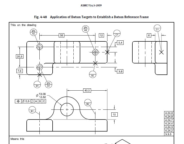
Question #1: I have an internal checker who is claiming that would be wrong (illegal) to add flatness on the surface where datum targets area A (Ø6) are shown.

By the same token,

Question #2: adding a perpendicularity callout (to A primary) for the surface where datum targets lines B are shown (considering that feature is continuous/planar and not, as shown, stepped, separated by basic dimension). The same checker is claiming that such approach is against the Y14.5 standard.

He does not want adding the perpendicularity (or flatness for that matter) because there are no figures in the Y14.5 where such method is shown.
Is this argument good enough to consider it valid? Is this practice against the standard?


Qff_-_Copy_scjtef.jpg
 
Replies continue below

Recommended for you

The standard concentrates on showing how controls work, individually, not on what combinations are suitable or useful.
 
His reason IS: BECAUSE datum targets are used (that's why no perpendicularity!! is this a "good enough" reaon: I don't know: I am asking)

If a part's function means that it's only being contacted at selected regions (thus the datum targets), then it's plausible that there need not be any explicit form or orientation tolerance to supplement those surfaces.
But it's a HUGE stretch to say that an explicit form or orientation tolerance would be illegal. The burden's on him to prove his case.

John-Paul Belanger
Certified Sr. GD&T Professional
Geometric Learning Systems
 
3DDave,
I do understand your latest replay, but that does NOT address my core issues regarding this matter.
A little more specificity would help tremendously.
 
Belanger said:
If a part's function means that it's only being contacted at selected regions (thus the datum targets), then it's plausible that there need not be any explicit form or orientation tolerance to supplement those surfaces.

Okay. Understood.

A quick follow up question: for the "missing" form and orientation tolerance to supplement those surfaces, would you consider that the general profile is applicable?
Pretend that "UNLESS OTHERWISE SPECIFIED Profile|xxx|A|B|C|" note is applied on the face of the drawing.
I am wondering if the general profile COULD take care of the missing relationship and missing form control .


Greenimi -- yes, that certainly would apply (and Rule #1 would control form, if nothing else).
But he might not even like the general profile idea, if he's that stuck on the notion that any tolerance on the surface is illegal!

John-Paul Belanger
Certified Sr. GD&T Professional
Geometric Learning Systems
 
Belanger said:
But he might not even like the general profile idea, if he's that stuck on the notion that any tolerance on the surface is illegal!
That would be true. I haven't brought that up to him, yet.

I guess, if just a little more clarity from the standard point of view, will come a long way to avoid that kind of discussions and issues in the industry.
I would like to say that some kind of harmonization between Y14.8 (Castings, Forgings and Molded parts) - where the datum targets were originated from - would only help.

For example Figure B-1, datum feature B is related with A (and A is identified with datum targets areas, BUT datum feature B does NOT have datum target identifications, so B is not a datum targets)
Now, you would argue that A is subject to rule#1, right? So, no need of additional form error control.
Is my assessment correct?


Are we still dealing with the internal checker's problem or has this gone off in some other direction?

There won't be any more clarity from the standard.

The need for additional form error control depends on the application.
 
Yes, I am still dealing with the checker's inability to understand that standard it is what it is.
I am still trying to get more ammunition to build up my arguments
 
Try showing him the Fundamental Rules in the Y14.5 standard.
I think these are the first two. The one that says that each feature shall be toleranced, and the followning one that says that dimensioning and tolerancing shall be complete so that there is full understanding of all the characteristics of each feature (and obviously that would also include the form of a datum feature, even when that datum feature is identified by the datum target symbol & not the datum feature symbol). If that isn't clear and unambiguous I don't know what is.
 
It seems your checker is suffering from the ole' "Missing the forest for the trees" paradox. I think he's one of those that get tunnel vision when looking at the standard not realizing that the standard can't cover every situation
 
OP said:
...where the datum targets were originated from

Is this surface "as cast"? Is the drawing in question of the casting, or of the product of further processing?

"Know the rules well, so you can break them effectively."
-Dalai Lama XIV
 
If I were to make a guess on why the standard generally avoids showing datum feature qualifying tolerances in the examples with datum targets, I would say it's because the figures would have to somehow deal with the problem that qualifying secondary and/or tertiary datum feature often requires ensuring repeatable inspection setup to be able to verify, for example, perpendicularity of feature B relative to datum A established from 3 datum targets that can literally be anywhere on the part when used alone (i.e., without invoking secondary and tertiary datum targets to fully immobilize the part relative to the datum targets simulator).

From what I see, the standard currently gives two options to handle this:
1. Use a note similar to the one given at the very end of para. 4.24.14 in Y14.5-2009, or
2. Control the secondary and tertiary datum features with tolerances referencing |A|B|C|, like in the car hood example (fig. 4-42 in 2009).

Either way, since this would require extra work on the drawing and might still potentially cause questions, the committee could have seen this as a good enough reason to deliberately leave the datum feature tolerance out, including the omission of form tolerances for primary datum features for consistency.
 
ewh said:
Is this surface "as cast"? Is the drawing in question of the casting, or of the product of further processing?

The surface is a plastic molded feature for an electronic enclosure (with mating surfaces, snap tabs, locator pins). From the supplier the mating surface came warped and distorted and engineering wanted to add flatness (for primary) and orientation (for secondary) to prevent those defects in the future. The bottom line: the box/ enclosure does not close properly.
But, as I stated before, the “issue” came that the checker does not accept those added additional controls because the datum targets are used. And datum targets are used because engineering thoughts were very much influenced by measurement / gaging techniques applied to this part. Incorrect, (to some extend) but here we are :)


Datum targets are indeed often used for establishing datums from datum features of inaccurate form. However, it does not mean that the form of those datum features can stay totally uncontrolled - that would be against the Fundamental Rules of ASME Y14.5. It simply means the form tolerance could be loose or result from other requirements such as a general profile tolerance or rule #1.
 
Instead of perpendicularity, use angularity to [A|B|C] to the surface.

Which engineering thoughts are "incorrect"?
 
3DDave said:
Which engineering thoughts are "incorrect"?

The ones that engineering were using datum targets (for measurement easiness, gage making process, reduce complexity of the inspection method with the gage, cost effectiveness of the gage) but they expected that the "entire" surface to act uniform for proper closure of the electronic box.
 
pmarc said:
Use a note similar to the one given at the very end of para. 4.24.14 in Y14.5-2009

Pmarc,
To be honest the first option you recommend me is a little over the top for my current level of education in this area of expertise. I am not understanding the intent of the note and how should I read it. I am afraid I have to do a lot of explaining to my fellow co-workers, if I chose option #1.
Again, at this point I am trying to understand your proposed solution if you can provide additional details, please regarding the pertaining note coped below.

DATUM FEATURES B AND C ARE INVOKED WHERE ONLY DATUM FEATURE A IS REFERENCED TO RELATE THE TARGETS THAT ESTABLISH DATUM A
 
The note would not be required for an angularity tolerance using [A|B|C] as the datum references. The note mentioned is for the purposes of using a control like Perpendicularity to [A], because simply saying Perpendicularity to [A|B] implies that the surface be perpendicular to both A and B. Using Angularity eliminates that implication.

---
The ones that engineering were using datum targets (for measurement easiness, gage making process, reduce complexity of the inspection method with the gage, cost effectiveness of the gage) but they expected that the "entire" surface to act uniform for proper closure of the electronic box.

Those two requirements can be separate. Targets are about how other features are controlled. Form controls control the immediate form.

In the grand scheme of things what they want is generally allowable. Anyone saying differently needs to show the full extent of the problem being managed to clarify why this particular case is or is not appropriate. Of course this case is apparently proprietary, so whatever effects are actually in play can never be revealed.
 
greenimi,

The way I understand the note is that it for geometric tolerances referencing A only, it "forces" the part to be set up against all datum target simulators (A through C), not just A,

Sadly, there is no example of the note application in the 2009 version of the standard. However, there is one in the 2018 (fig. 9-16), and it is there because installing the part against datum targets A only for the perpendicularity tolerance measurement would result in infinite number of possible relationships between the part the datum target A simulators. In other words, the setup would be far from repeatable.
 
Status
Not open for further replies.

Part and Inventory Search

Sponsor