Eng-Tips is the largest engineering community on the Internet

Intelligent Work Forums for Engineering Professionals

Datums

Status
Not open for further replies.

ozzy1

Mechanical
Feb 9, 2011
30
0
0
US
I am head of QC in a manufacturing company full of engineers and I am constantly arguing with the engineers especially the younger right out of school types about the correct way to detail their drawings.

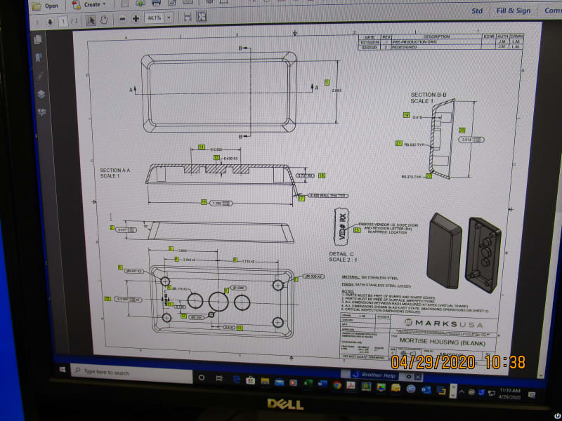
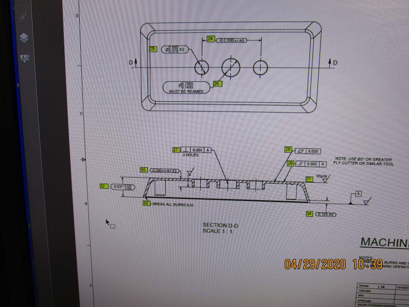
The latest concerns Datums. This engineer continually places Datums on cross sections. Right now we have a
3-D cover that in one view, a cross section that cuts through half of the part is placed a datum. This Datum is then used to relate parallelism and machining requirements. My argument is that the Datum only covers half the part.

Am I being too picky
 
Replies continue below

Recommended for you

If its clear what surface is being referred to, there is no issue in showing it in a detail/section view. That does not by any means dictate that it refers to only part/half of the surface/feature specified unless it it accompanied by one of several notations to designate otherwise (ie: chain line, limited area/length, datum target, etc...). If you go by Y14.5 there are many examples of such a practice, one of them is below. I don't think the story is any different with ISO.

7-24_dldiii.jpg
 
I've never seen a problem with putting a datum on a cross section view or ever heard anyone say that the datum only consisted of half the surface.

----------------------------------------

The Help for this program was created in Windows Help format, which depends on a feature that isn't included in this version of Windows.
 
Attached are the pictures of sheet 1 and 2. It is my view that the call-outs in question should be detailed on the side view (3rd view down) on sheet 1 not on a cross section on sheet 2.

IMG_0254_y3ug1n.jpg
IMG_0255_lpifgm.jpg
 
It seems pretty clear what is being referred to as datum feature A. I see no reason why it MUST be on the side view - it comes down to personal preference.

To be sure, specification of a datum feature on a section/detail view does not change what that datum feature looks like or how it is established - the same as a diameter tolerance on a section view does not imply it applies to only half the diameter. Indeed a section view is sometimes the only way to properly show a particular feature.

fig_2-6_vheqav.jpg


fig_3-4_gkb7js.jpg
 
ozzy1,

Good drafting is a lot like good writing. Closely related information should be grouped in close proximity. Most of the GD&T is on the section view on sheet[ ]2, making it good place to call up the datum feature. The drawing has not been the way I would have done it, but I can make sense of it.

--
JHG
 
ozzy1,

What standard is this subject to - is it ISO? I see a redundant flatness callout, perpendicularity applied to a center line instead of the feature or diameter dimension, and *several questionable symmetry specifications without datum feature references and also applied to hole axes. None of these is really acceptable in ASME (except for the redundant flatness - this would be more like poor practice), but perhaps the story is different in ISO.

*I realize now these are not accompanied by a tolerance value for a geometric tolerance. It seems I've seen this someplace used in a similar manner, but I confess I'm not sure exactly what its meant to communicate. Implied symmetry of the hole location about an implied datum feature - perhaps the reamed hole between them? This combination of symmetry and +/- directly toleranced location of a feature has no meaning in ASME and I'd be skeptical it does in ISO - to my knowledge both documents recommend against +/- tolerancing of feature location as it is. Do you have an internal document to support this use?
 
Status
Not open for further replies.
Back
Top