Continue to Site

Eng-Tips is the largest engineering community on the Internet

Intelligent Work Forums for Engineering Professionals

  • Congratulations KootK on being selected by the Eng-Tips community for having the most helpful posts in the forums last week. Way to Go!

design of ladder stiles 2

Status
Not open for further replies.

LAZAR90

Petroleum
Aug 17, 2020
24
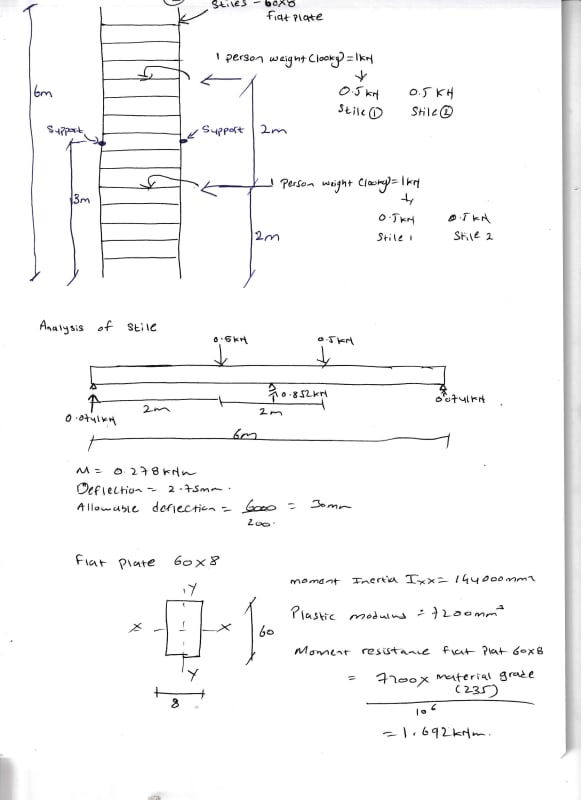
IMG_20220720_0001_xfpwje.jpg
[URL unfurl="true"]https://res.cloudinary.com/engineering-com/image/upload/v1658321394/tips/IMG_20220720_0001_ixcvui.pdf[/url]Hi
Can i have some advice on design of ladder stiles.
thanks
 
Replies continue below

Recommended for you

When you say "stile", I picture something like the attached, which seems to be different from what you're doing. So what exactly are you designing?
Stile_gilhjb.jpg
 
I've seen the 'side rails' referred to as 'stiles.. not often, but has happened. I don't know if 'side rails' is the correct term.

From my Project Notes:

-DESIGN LOADING:
DL AND LL FACTORS FOR LADDERS, AND GUARDS BOTH ASSUMED TO BE 1.0;
RUNGS AND ACCESS STAIRS 1.32KN (300LB) AT ANY LOCATION EACH 10’ OF HEIGHT IN ACCORDANCE WITH ASCE 7;
1.2KN (250LB) AT ANY LOCATION ON ANY TWO ADJACENT RUNGS IN ACCORD WITH ANSI A14.3;
LADDER RAILS 4.448KN (1000LB) VERTICAL AT ANY LOCATION;
LADDER LOAD IS SHARED BY 4 FASTENERS;
LADDER DEAD LOAD SHALL BE LESS THAN 75 LBS PER FASTENER;
LADDER RAILING AT TOP IS NOT DESIGNED AS A GUARD; AND
LADDER RUNGS SHALL BE NON-SLIP.
-HEIGHT OF LADDER MARGINALLY EXCEEDS 5 M. A VARIANCE SHOULD BE OBTAINED FROM THE AHJ TO PERMIT ACCEPTANCE.
-SUPPLY AND INSTALL BILCO LADDER UP SAFETY POST MODEL LU-4 ALUMINUM OR APP’D EQ


So strange to see the singularity approaching while the entire planet is rapidly turning into a hellscape. -John Coates

-Dik
 
ladders-f-2021_gcg5q5.png


The arrow shows what i am designing in the ladder
 
dik,

I'm not familiar with the ANSI A14.3 - what's the purpose of the (2) 250 pound loads on adjacent rungs? Are those loads vertical only, or are they a moment couple?

Please note that is a "v" (as in Violin) not a "y".
 
I'm not sure... just to provide an extreme overloading? You would think the agencies could put their minds together and come up with a uniform loading requirement.

So strange to see the singularity approaching while the entire planet is rapidly turning into a hellscape. -John Coates

-Dik
 
On the original diagram, it looks like you're checking moment in the ladder without considering the intermediate supports.
Required ladder load and safety factor will vary depending on the applicable codes- may be from OSHA, ASCE 7, etc.
I assume the two loads represent two climbers spaced out.
 
I could buy the (2) 250 lb loads as 2 climbers if they were spaced even 2 rungs apart, but dik's notes say that those are on adjacent rungs. Not saying that it couldn't be 2 climbers, but you'd really have to work at it to stack up like that.

Please note that is a "v" (as in Violin) not a "y".
 
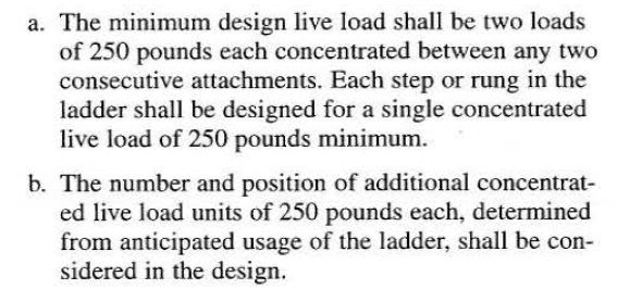
I've been designing them wrong for years... A14.3 states:

Clipboard01_jftg7x.jpg


It doesn't cause a problem because the loading doesn't impact the rungs or the side rails... but program fixed and notes revised... thanks.

Note Revised to... "1.2 1.1KN (250LB) AT ANY LOCATION ON ANY TWO ADJACENT A RUNGS IN ACCORD WITH ANSI A14.3;" I cannot edit the original posting.

So strange to see the singularity approaching while the entire planet is rapidly turning into a hellscape. -John Coates

-Dik
 
I would interpret that note a little differently. Attachments are not rungs. See below.
Also, 1.2kN is 270LB, not 250.
Capture_ugqu1z.jpg


BA
 
BART... I think you're correct and have adjusted my notes and program to suit. and load was changed to 1.1kN... thanks.

So strange to see the singularity approaching while the entire planet is rapidly turning into a hellscape. -John Coates

-Dik
 
Status
Not open for further replies.

Part and Inventory Search

Sponsor