Continue to Site

Eng-Tips is the largest engineering community on the Internet

Intelligent Work Forums for Engineering Professionals

  • Congratulations KootK on being selected by the Eng-Tips community for having the most helpful posts in the forums last week. Way to Go!

Design trailing arm suspension 2

Status
Not open for further replies.

Spanish Wells

Agricultural
Jul 25, 2020
39
Hi to all; I wonder if someone could help me please ?
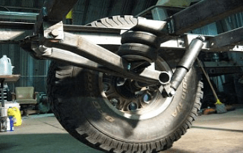
I'm designing / building a trailer using a trailing arm suspension system. My problem is to design the arm to accommodate the torsional stress involved.
The wheel / tire is 32" diameter, 10" wide.
Static load of 4,000 lbs per tire.
The stub axle(inc brakes) will be attached to an arm approx 20" long from axle center to pivot point.
This arm will be a "bell crank" transferring suspension loads to an air bellows suspension.
My problem is to specify the section of the arm to resist the torsion loads.
I want the arm to be as thin as practical to minimize the overall width of the system.
My thoughts are to flame cut the arm/bell crank from A36 structural plate of the appropriate thickness.
Could somebody help with the appropriate formulae so I can look at various sections of the arm,
for example: what width would I need for 1" plate, or 1.5" plate, etc.
I'm thinking I could build a table using Microsoft excel to include all the variables such as: load, g force, twisting moment, length of arm, material thickness, material width, mechanical properties of the steel, etc and play with the section of the arm to give me a good solution.
Appreciate any help.
Bob
 
Replies continue below

Recommended for you

The reason for solid bar is two fold - 1) the gain is not much, but still save space where fraction of tenth of inch counts, and 2) did you check torsional stress combined with shear, V = F*FOS = 7000^2 = 14000 #.
 
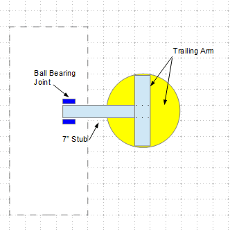
This is what I have imaged. BTW, you can draw using "OpenOffice" drawing module (free), and copy to the clip board by "Shift+window key+s", then paste to the image box (with pic of camera) of this forum by "Ctrl+v".

image_yw93tr.png
 
Retired
I'm OK with an extra 1/2" section width, thanks.
No I did not check torsional stress combined with shear.
 
I will give the usual caveat here - you should engage an engineer before you build anything. IF you want this trailer to be road legal and registered, your chances are much higher if a licensed engineer has reviewed the design before you waltz on down to the DMV and have to argue about whether or not it is safe.

With that said...

If you do this with plate, the torsional loads will be immense. But you also need to take into account that stiffness is your limiting factor here.

If the trailing arms aren't stiff enough, the tires will move all over the place, and this will make the trailer very dangerous to tow. If you make them out of plate and size the arms such that they provide sufficient stiffness, they will be gigantically heavy and difficult to fabricate. Trailers, racecars, and other things that need to be strong and light weight use tube instead of plate for a good reason.

What you really need is to come up with a detail that links the pairs of wheels together across the frame member. This would cancel out your bending moment- your stub axles or thru axle will need to be substantial, and the bending moment in the trailing arm will also be substantial, but your trailing arm bushings/bearings/linkage will see zero torsion and will be much easier to make strong and reliable.

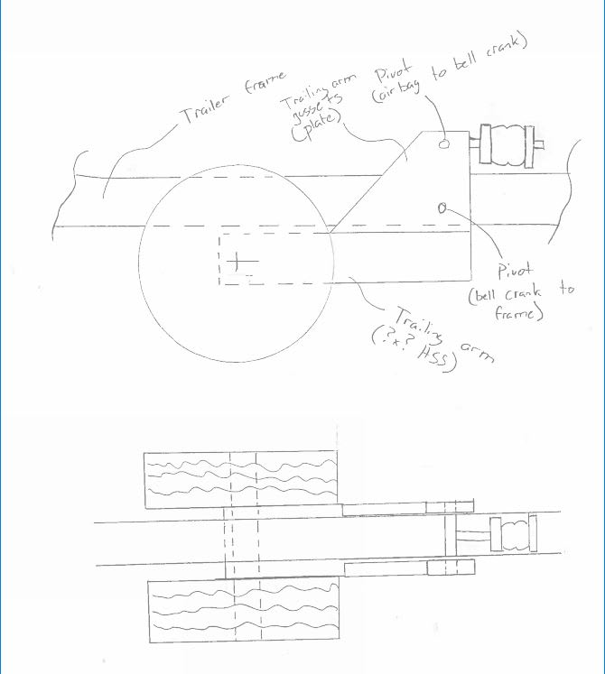
Here's a very simple arrangement. With some clever packaging you could 'hang' the frame under the wheel centerline, although that flips your bag 180 degrees and puts it underneath the frame, which has complications. Much depends on how low you need the trailer to drop, and how much time you're willing to spend designing.

The quick sketch below shows this arrangement lowered all the way down- the size of the wheel/tire and the section used for the trailing arm will have a direct impact on your lowered height. Remember that you can't lower the axle centerline unless you plan to air down the tires for loading/unloading, and even if you do that you won't gain much. So if you design all this out, member sizes have a huge effect on functionality.

Capture_hfq6hf.jpg


A word on your stress calculations - there's zero reason you would ever use round tube for this. Square tube will be significantly stiffer and easier to fabricate.

Remember that your trailing arm does not see only torsion - it sees torsion AND a giant bending load. Calculating this combined stress state is difficult.

Also - 1+ degrees of deflection is a LOT. There's also considerable side load coming into play any time this trailer gets dragged around a corner. Side load is going to try to bend your trailing arms side-to-side, and if you don't have enough stiffness in that plane, the trailer will not behave in a predictable way.

Towing your 24,000 lb boat behind an 8,000 lb truck at 50 mph on a trailer that isn't predictable is going to be very, very dangerous.

In short, your trailing arm needs to be designed to handle the worst case loading. As a rough guess, that includes:

-Lateral loading of probably at least 2G (you'll see this at minimum if you need to do a hard lane change in an emergency, such as someone pulling out in front of you)
-Impact load in the bump direction, such as hitting a big pothole (this varies a lot due to a lot of factors including how much damping; 8-10G is in the realm of possibility without sharpening your pencil too hard. This load is huge)
-Longitudinal load of at least 1G (max braking)

Plus whatever loads exist with the trailer not moving in a parking lot (i.e. all your static loads discussed above)

All multiplied by a reasonable safety factor.

Your system has to be sized to handle all of these loads at the same time- not just one of them.
 
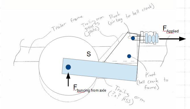
This is my understanding. For properly designed towing frame, the trailing arm resists the applied force only, provides all pivot points are rotation free.

image_lpbik8.png
 
Swinny
Thank you for taking the time to contribute.
I do not want to be seen to be defensive here. Just to discuss your thoughts.
My background is a retired Production / Industrial Engineer from the UK, living in the US the last 30 years; working with a major tire manufacturer.
I have built several trailers over the years, generally in 12,000 lb gross range. This is something new.
I think you will see that I've moved off the naive idea of plate, following input received from this site.
If you take a look at the images and links that I posted you will see some similar designs. One of them with dual tires rated at 6,000 lb each, using some form of trailing arm solution as I'm looking at. Due the fact they are using duals, the center of the load is further from the trailing arm, than I'm considering, but also they have twice the loads, because of the duals.
My intention is certainly not to tow this trailer behind a pickup truck, but will use a contractor who typically tows mobile homes.
I need to keep the boat as low as possible due to bridge clearance. I will use detachable cross members, maybe 4" square, not defined yet. I would like to achieve 8" ground clearance beneath the cross members. For simplicity in designing the cross members, this puts the bottom of the trailer frame at 12" from the road, in the travel state. I could then lower the trailer up to 8", depending how I attach the cross members, for loading.
It would be difficult to link the trailing arms below the frame to achieve this. Maybe they could be linked above the frame ? Tires are 32" diameter, so 16" center height.
Because of these issues and looking at the other designs above, I'm thinking of wheels on the outside of the frame only.
The challenge is the design of the trailing arm. The static loads are easy to define, the dynamic loads maybe not. In attaching the trailing arm to the frame, it should be possible to achieve stiffness in the pivot, as the pivot arrangement could be as much as 12" to 16" long. This will minimize the stability issues you cite above. As you have pointed out,there are several loads:
- torsion load from the cantilever of the stub axle
- bending load in the trailing arm due the weight, and suspension reaction
- lateral loads from maneuvers, be it in a parking lot, or lane change. You suggest 2g. 2g times what load ? The total load of the trailer ? Divided by the number of tires ?
- maybe there are others...
Thus far I've considered the torsional load, with a factor of 3 for shock loads. Maybe this is insufficient - I'm open to input based on industry standards or first hand experience, please.
I've not considered bending force from suspension loads, however I could "triangulate" trailing arm to create a more direct link to the air bag, and therefore minimize the bending load. This would also aid in adding torsional stiffness.
I not sure the lateral loads are that significant. I would imagine the other loads are more significant, particularly if the trailing arm is sized for those loads, with whatever factor is appropriate.
I have considered round tube as this would be the best solution, believe, for the torsional loads; and I do not know how to calculate torsion loads in square tube. Maybe square tube would be a better solution for the combined loads.
I have not yet had a chance to put eyes on one of these other designs - something I intend to do.
It is also my intention to get an Engineering stamp for DMV and insurance reasons. I want to present a design for consideration.
Once again, I appreciate the input, and hope I do not appear to be too defensive.
Thank you
Bob
 
If my sketch above is ever close to the central topic, for loads depict, I don't see torsion but bending - from the stand up trapezoidal plate to the trailing arm. However, for side swing (lateral) load case, torsion is possible. Again, I don't know anything about automotive design, just straight talk on simple mechanics for the given setups. Hope more automotive/mechanical engineers can join the discuss, and provide meaningful insights.
 
Torsion is generated because the load applied to the trailing arm (the lower and left most of the two forces in your diagram) is eccentric- it isn't applied along the centerline of the trailing arm. It's out of plane towards the viewer of your diagram.

Bob,
You don't sound defensive at all. I hope my post is not interpreted as an attack.

Square tube is less stiff in torsion per lb (this is a generalization but it's a reasonable rule of thumb) BUT it's MORE stiff per unit of volume. Airplanes and race cars use round tube for their space frames because they care very much about stiffness per pound. Buildings and other structures where weight does't much matter will almost always use square sections. This trailer of yours is probably going to weigh as much as the boat if you want to carry it safely. At that weight, a few hundred extra pounds in your trailing arms won't matter but the 20% stiffness you will gain will matter a LOT.

Regarding the torsional load in the arm- any suspension load applied (such as striking the edge of a pothole) adds to both the bending load and torsional loads applied. If you want to be safe, with a single tire outboard of the trailing arm, the trailing arm needs to be able to handle that impact, which is the 8-10 G number I listed as a starting point. There are people in the world who have great models of what the real loading is when a tire hits a pothole or a curb; unfortunately for the home gamer, those people all work for automotive or equipment manufacturers who REALLY don't like their models, and the secret sauce contained therein, getting out into the world.

When we're talking G in suspension, that's against the total weight of the trailer and cargo. If your fully loaded trailer weighs 100,000 lbs, has 6 wheels, and hits a pothole that puts 10 G of load into any one wheel, that wheel must be safe to a true load of ~160,000 lb. (100,000 / 6) x 10.

That sounds like a huge number (and it is) but that's the nature of building equipment to move giant objects.

2G in cornering would be 32,000 lb side load (per tire for that same 100,000 lb 1x6 trailer) ; and again, you have to size everything to provide enough stiffness that the deflection at that load doesn't send the trailer off into the ditch pulling the rig behind it.

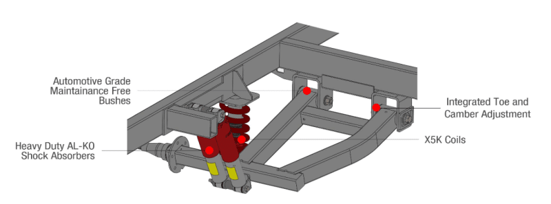
The trailer manufacturer linked above has some fairly revealing pictures of their suspension on the site if you dig around.

Link

That trailer is listed as having a 10" x 10" frame, and the trailing arms appear to me to be very close to the same size; perhaps 10x10 or 10x8. Also take note of the thickness and length of the gussets and mounts which support the pivot pins. Everything mounted to that trailer is beefy.
 
Swinny,
Thanks again for the input.
Can you point me to a calculation, or equations for torsion in square tube please ? I've not found anything.
Your comment regarding the swing arm being same size as the frame - in that design that arm you refer to pivots to raise the whole trailer some 24" plus for loading. The actual suspension is attached to that arm.
A photo on page 3 of their brochure shows this feature.
Thank you
Bob.
 
Wells,

This site can help for torsion on rectangular hollow shape. Link
 
Retired
Is the link correct ? It comes back to this post.
Bob
 
Something for you to consider. The forces on the trailing arm are quite manageable, but attention should be focused on trailing arm to tire connection, that is to take a lot of abuses.

image_fav2cg.png
 
Regarding loads to be considered in this design.
In theory, the acceleration of the wheel hitting a 6" high curb at 50 mph could be calculated, but this would be quite complex as it needs to include the spring rate of the tire, suspension, and any other member that deflects under this load.
An alternative would be to see what others have designed, and back into their assumptions.
If we take a Dexter 10,000 lb capacity trailer axle,with a 5" diameter, 1/4" main tube.
The track width is 70", spring center 42", and they probably use 1026 steel or similar.
MoI of axle tube 10.55
Max stress at 1 g = 16,600 psi (5,000 x 14 x 2.5 / 10.55)
Yield stress 60,000 psi.
It seems they have considered <4g in their load calculations.
 
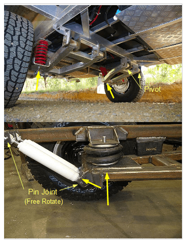
The view of this one is clearer.

image_rgd68h.png
 
Another similar but much stiffer design. As the concept is getting clear, I suggest to open a new thread on the automotive forum, from which you shall get plenty of to the point advices. Good luck.

image_mpkinh.png
 
Retired
I tried your link, but it won't open for me.
Not sure if there is a daily limit on how many times you can enter the site, as a guest, or whether this is in the "not free" area.
Thanks
Bob
 
Status
Not open for further replies.

Part and Inventory Search

Sponsor