Continue to Site

Eng-Tips is the largest engineering community on the Internet

Intelligent Work Forums for Engineering Professionals

  • Congratulations KootK on being selected by the Eng-Tips community for having the most helpful posts in the forums last week. Way to Go!

Design trailing arm suspension 2

Status
Not open for further replies.

Spanish Wells

Agricultural
Jul 25, 2020
39
Hi to all; I wonder if someone could help me please ?
I'm designing / building a trailer using a trailing arm suspension system. My problem is to design the arm to accommodate the torsional stress involved.
The wheel / tire is 32" diameter, 10" wide.
Static load of 4,000 lbs per tire.
The stub axle(inc brakes) will be attached to an arm approx 20" long from axle center to pivot point.
This arm will be a "bell crank" transferring suspension loads to an air bellows suspension.
My problem is to specify the section of the arm to resist the torsion loads.
I want the arm to be as thin as practical to minimize the overall width of the system.
My thoughts are to flame cut the arm/bell crank from A36 structural plate of the appropriate thickness.
Could somebody help with the appropriate formulae so I can look at various sections of the arm,
for example: what width would I need for 1" plate, or 1.5" plate, etc.
I'm thinking I could build a table using Microsoft excel to include all the variables such as: load, g force, twisting moment, length of arm, material thickness, material width, mechanical properties of the steel, etc and play with the section of the arm to give me a good solution.
Appreciate any help.
Bob
 
Replies continue below

Recommended for you

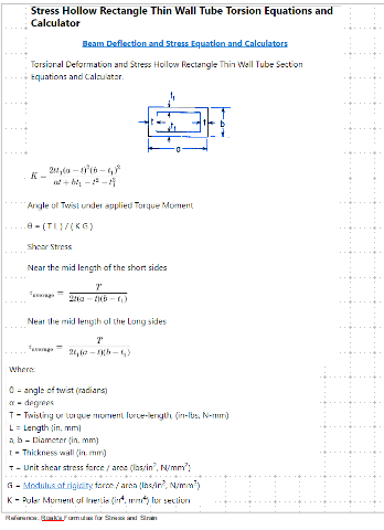
The link works for me. Maybe there is a problem with your browser. Anyway, here is the formulas. Also try this link.

"
image_odcdzl.png
 
You are welcome. Hope things work out for you.
 
Spanish Wells said:
Your comment regarding the swing arm being same size as the frame - in that design that arm you refer to pivots to raise the whole trailer some 24" plus for loading. The actual suspension is attached to that arm.

I agree, but that trailing arm sees the same torsional and suspension loads, in a similar range to what you're designing.

I'm not saying your member sizes will need to be exactly the same as that, but other designs in this load range should provide a good sanity check as to how close you are to what's already known to be durable out in the world.

The designs posted by others are instructive, and may help you work out some packaging challenges, but they are for MUCH smaller trailers with much lower load capacities.
 
Swinny,
So, working on your suggestions, and some calculations Retired has steered me towards, here is my thinking:
6 tires, 3 each side on outside of trailer.
Capacity of 5,000 lb per tire.
Trailing arm length = 14.5"
Small bending stress, as triangulated directly to spring.
Length of stub axle = 12" - will hopefully be able to shorten.
Trailing arm square tube: 4" x 4" x 3/8"
Torsional Stress calculation = T/((2t).(a-t).(b-t1))
T = 5,000 lb-ft
t (t1) = 0.375"
a (b) = 4"
g force = 8, so T = 40,000 lb-ft
Stress = 48,700 psi.
I don't know how to calculate the twist in a square tube, but the same load applied to 4" dia x 3/8" round tube gives 2.1 degrees. ( and a stress of 67,000 psi) so I should be perhaps 1.5 degree.
This is a massive structure, but I have considered 8 g.
If I go to 5/16" wall tube, and 6.5g, then my stress stays at about 44,000 psi.
Is my logic sound, please ?

Next I need to think about the torsional stress and deflection in the side beams. 10" square by 40 ft long. Going to need lots of well attached cross-members !
Thanks
Bob


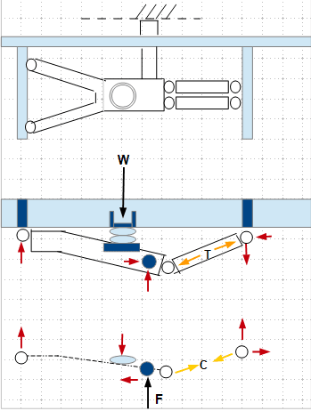
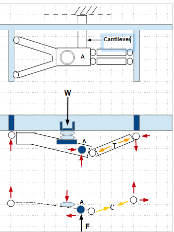
The sketch below is force diagrams for one of the design. There are two cases considered, 1) static weight, and 2) impact due to tire bouncing upward. For road drive, case 1 and 2 are to be superimposed. Force to trailing arm-tire connection should be calculated using the net force at point "A", with the linkage as a cantilever beam. The diagrams need to be blessed by an experienced design engineer, and you might need his/her help as the calculations are quite involved

Legend: Black Arrow - Applied Load, Red Arrow - Joint Reactions, Yellow - Cylinder Internal Force

image_s223fm.png
 
"In theory, the acceleration of the wheel hitting a 6" high curb at 50 mph could be calculated,"

No they can't - that's my job, and I always start with actual measured data, of some form, typically a few strain gages or a load cell in the road.

Cheers

Greg Locock


New here? Try reading these, they might help FAQ731-376
 
Pointing out avenues that do not work may not seem very helpful, but can stop you wasting time. You can't calculate the loads accurately, the ones you started with were hopelessly low, somebody came up with some more sensible looking ones. Since I haven't measured trailer loads I'm not going to suggest specific numbers.

Cheers

Greg Locock


New here? Try reading these, they might help FAQ731-376
 
Retired
Thanks for your contributions. The approach you're suggesting doesn't fit my need because to get the overall suspension movement I'm looking for I must have all the components on the out side of the beam.
I have seen the style you are looking at, particularly on extreme offroad camping trailers.
Bob
 
Spanish Wells

I've greatly enjoyed this post, but looking back through it all I'm really wondering if you've bitten off more than you can chew.

From the above you are apparently trying to create a road transporting boat trailer capable of shifting (your?) boat which weighs around 12 tonnes and is 42 feet long, 13 feet wide and 12 feet high.

This is not like building a boat trailer to tow behind your car as I think you're discovering. The forces are huge and if it goes wrong you could loose a wheel, have your boat turn over and cause a large crash. If it's your boat then fine, but the insurance won't be paying out when they find out you made it in your back yard.

The second main issue I think you really need to give some intense thought to is whether you really need as oposed to would like, this whole lift up and down business on the suspension and more to the point do you really need to lower the frame below the centre of your wheel. This is really quite hard to do and if you can keep the frame above the centre of the wheel at all times then it would get a LOT easier. If you look at the examples above I think you'll find they all work on the principle of the stub axle being below the line of the frame.

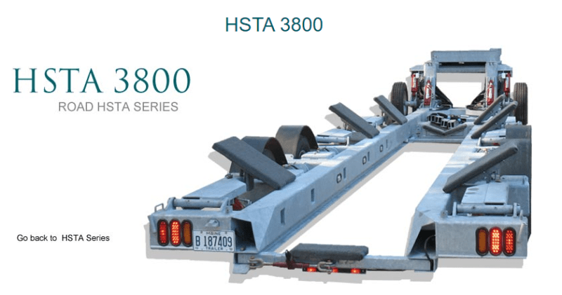
When you look at the example you posted from hostar marine which is less than your capacity - it is a beast of a trailer. There is a good reason why they will cost a lot of money. Mainly because they don't want to get sued if the trailer falls a part in use.

image_kxhqcd.png


So I wish you luck and would love to see more information, but hope you sit back for a minute and decide if this is real or just a fantasy to build it and actually use it on the public highway. In a boat yard - No problem. On the Road - I struggle to see it happening.

Remember - More details = better answers
Also: If you get a response it's polite to respond to it.
 
LittleInch
Thank you once again for your contribution.
I accept all of your points, and it's good to have a conservative point of view, as a challenge to the thinking.
Clearly this is a massive structure. Initially I underestimated the loads involved - certainly one of the main reasons I posted on here to get better information.
I have access to a fabrication shop, and professional welders.
It is my intention to get an Engineer to review the drawings, for all the good reasons.
The main structure of the trailer is quite straightforward. Clearly all the brackets, plates, gussets etc will need to be very substantial, "over-engineered".
The suspension bellows I'm looking at are Firestone IT15L 4 bellows:
They have a stroke of 9.5", load capacity of 7,000 lbs at 100 psi. I don't need this much capacity, so can increase the wheel movement with appropriate lever ratios. This is how I can fairly easily raise and lower the trailer, within a limited range. See page 92 in Firestone literature.
I hope you will notice that I am very open to input, to challenge my ideas, and develop a good, robust solution.
My plan is to continue with the design process, looking for solutions to each of the challenges.
I have found appropriate axles/brakes/hubs/wheels/tires.
I feel my trailing arm design is sound, although I've not yet identified pivot bushes.
I have identified suspension bellows that give me the features I'm looking for.
I have decided on the main structure frame members.
The next step is to consider the dimensions and how to attach my cross-members so they are easily installed/removed, but the attachment gives the necessary torsional support to the main beams, and supports the load.
At the end of this process I will seek a professional review of the design.
I will also get "eyes on" other designs, so as not to reinvent every aspect of the wheel.
I may ultimately decide this is not a good idea - I'm not there yet.
Once again, thank you for your constructive contributions.
Bob
 
OK, this is making more sense and sounds like the real deal, thanks for responding.

The issue remains the amount of lift and the lowest position you want the trailer frame to get to relative to the wheel. Anything above the axle height is I think much easier to design

Then what is your minimum gap between your forks?

If you look at all the other examples and what people have drawn, everyone of the trailing leg type designs are some sort of wishbone which you need to avoid huge moments at the joint between the single trailing rod / bar/ tube and the pivot tube. This needs space.

I can't see the details on the trailer picture above, but looks like it might be a sideways wishbone to me.

Rather than this complex armand pivot arrangement I think you'd be much better off with the air spring acting directly over the stub axle connection onto the trailing arm. Removes large amounts of stress, moments, gusett plates etc and all your arm is then doing is keeping the wheel in position and transmitting braking forces.

Think you need a trip to a boat yard or three and do a bit of peering about under some trailers....


Remember - More details = better answers
Also: If you get a response it's polite to respond to it.
 
LittleInch
Once again thanks for your input.
I'm trying to avoid having any part of my swing arm arrangement under the trailer frame.
The reason for this is that the tire is 32" diameter, and stub axle tube 5"; so that would mean minimum frame height 19". If I then add suspension travel of 10", everything gets very high.
It makes the attachment of the cross-members then quite complex to keep the boat low.
You are correct about the moments generated by this approach. I am waiting for the actual dimension from Dexter for wheel hub face to back of brake drum. It seems to be in the order of 12". The wheels need to be centered over the hub, for bearing life. So this seems to force me into this 12" stub axle - creating this huge moment at the end of the trailing arm. I can reduce the effect at the pivot end by extending the pivot point in front of the tire and under the frame, and gusseting accordingly.
The bell crank arrangement allows me to lay my bellows flat with about 12" above the frame member. It allows me to choose a leverage ratio to maximize suspension travel with bellows load capacity.
If I stand the bellows up, max height is 16".
Hmmmmmmmm
I wonder if I can find a higher capacity bellows, that would not be as tall, and position it directly on the trailing arm as you have suggested.
All part of the design process.
Thank you for your input.
Bob
Dexter 10,000 lbs hub arrangement:
 
I am getting addict to this thread, and have learnt quite a bit of mechanical/automotive setups. Don't stop posting the idea you have came up with, an updated plan and cross section will be of great help. I am thinking your original plan, seems doable, but I need time to visualize it. Is the 7000# the towing force on a single arm? What is weight of the boat?
 
Retired,
The math has evolved as different solutions appear.
The weight of the boat is 24,000 lb, supported on 6 tires.
So with the weight of the trailer itself, I'm using a design load of 5,000 lbs per tire.
That is the load supported by each tire, and therefore each suspension trailing arm.
Thank you
Bob
 
I think your trailer will end up weighing a bit more than 3 tonnes...

Remember - More details = better answers
Also: If you get a response it's polite to respond to it.
 
Status
Not open for further replies.

Part and Inventory Search

Sponsor