Continue to Site

Eng-Tips is the largest engineering community on the Internet

Intelligent Work Forums for Engineering Professionals

  • Congratulations GregLocock on being selected by the Eng-Tips community for having the most helpful posts in the forums last week. Way to Go!

Determine cylinders for my system. 2

Status
Not open for further replies.

emerald11

Mechanical
Nov 26, 2017
8
Hi!

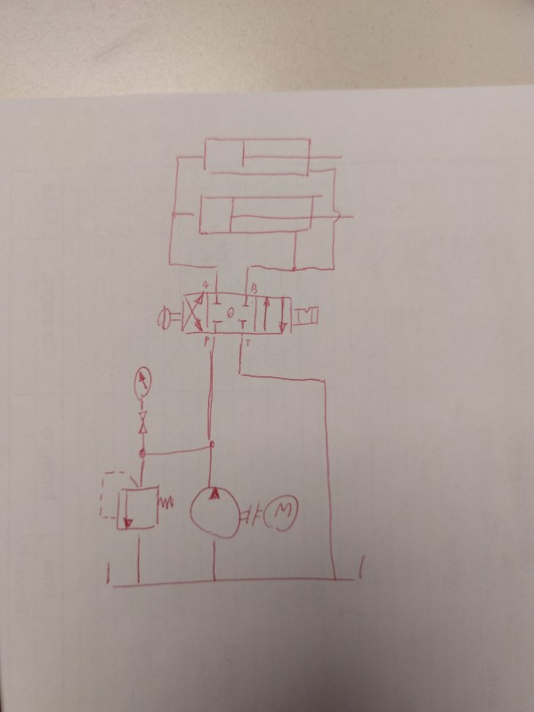
I have constructed a simple hydralic system (on paper) that should be able to open a cargo door.
As you can see it will have 2 lifting cylinders. To open the cargo door a force of 45kN is required for each cylinder.
The stroke has to me 600mm.

The pump that will be used:
Deplacement : 24cm3 /revolution
max pressure : 200bar
efficiencies for the pump is nvol 95%, nhm 95%.
initial speed of the pump is 1100 rpm

I have an hard time finding good cylinders that are fairly common on the market for this job.
What cylinders would be best for this job? Model name? (so i can order it and download the data sheet).
Thanks in advance.
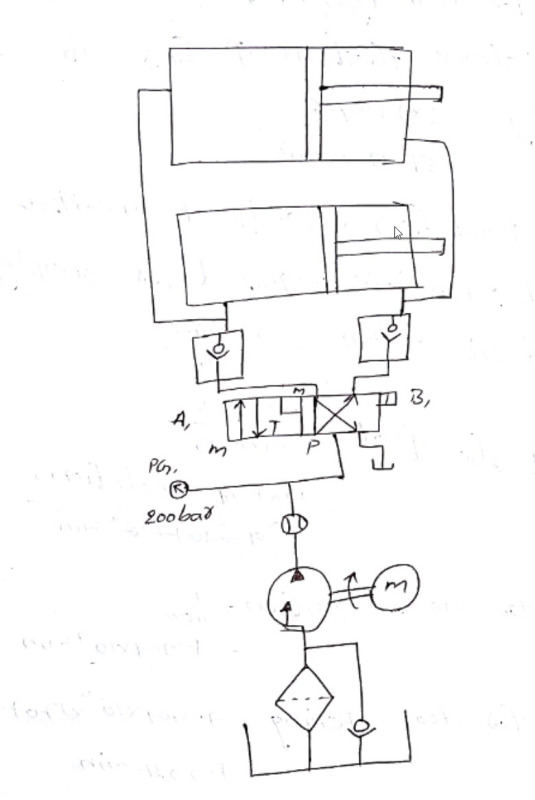
hydraulic_scheme_vxjs1r.jpg
 
Replies continue below

Recommended for you

That is ugly. The check valves to the cylinders will prevent flow trying to exit the cylinders. Use a return line filter, not a suction filter. Why a check valve on the pump intake to tank? Why not use just one cylinder? How does the pump unload when the cylinders reach full stroke?
What problem have you had finding the cylinders you want?

Ted
 
hydtools said:
That is ugly. The check valves to the cylinders will prevent flow trying to exit the cylinders. Use a return line filter, not a suction filter. Why a check valve on the pump intake to tank? Why not use just one cylinder? How does the pump unload when the cylinders reach full stroke?
What problem have you had finding the cylinders you want?
Hi Ted and thank you for your reply, i really appreciate it!

# The check valves at the cylinders were my try to stop the hatch from going down again in case of leakage in the direction valve.
# Regarding the filter i just did not think it did matter if i had it as a suction filter or as a return line filer.
# About the check valve on the pump intake, i honestly now after i draw the scheme don't really know why i did put it there.
# I was thinking of having two cylinders to more easily even out the weight of the hatch
- I see now that i used two double-acting cylinders, but since the weight of the hatch itself should be enough i could go with two single-acting cylinders?
# The problem i had with finding the right pump is that i really don't know what would be a decent pump.

I tried calculating with an 125mm bore size with a stroke length of 600 mm and came to the conclusion it would take 35.5 sec to open the hatch.
Is it just that easy that i look for any cylinder whatsoever that fulfill my calculations to a "decent" amount of time for the opening of the hatch?
I just don't want to have the cheapest possible items to do the trick.
# On a sidenote: if a professional engineer would design such a system, would it differ a lot from my drawings? What would it look like?
 
I think 125 mm bore is too much for your application.
With 160 bar a 60 mm bore have a pushing force of 45KN.
 
gersen said:
I think 125 mm bore is too much for your application.
With 160 bar a 60 mm bore have a pushing force of 45KN.
Thank you for your answer!.

Yeah i think i was aiming for an to big bore size. I would like to have the hatch open alot faster aswell.
I am still somewhat uncertain on how the acctually schemeatic would look on paper.
I tried to draw it in fluidsimulation, with some adjustment that Ted talked about in the response above , but still dont really know how an "real" engineer would draw a system like this.

 
I'm not an expert. But I think something like this
15118725498161595904807_skzm1q.jpg
 
gersen said:
I'm not an expert. But I think something like this
Thank you, really appreciate the feedback!

One question, the cylinders do they need to be double-acting? Since the hatch itself should have enough weight to pull the cylinders back into place?
-if i use an single-acting cylinder, do i need to compensate with some kind of damping effect so the hatch wont just slam right back with force?

So it is an directly controlled pressure relief valve on the left? that i set nominal pressure to these 200 bars?
Does this system guarantee that the system wont lower the hatch in case of internal leakage in the direction valve?
 
You could use pilot operated check valves to lock the cylinders when the directional control valve is centered.
For single acting cylinders you can use a flow control with a bypass check valve to control the hatch closing speed.
You should add an unloader valve to unload the pump when the directional control valve is centered.
Ted
 
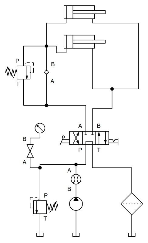
I did try to draw it in a program.
This is the result.
test_b3w1sh.jpg
 
hydtools said:
You could use pilot operated check valves to lock the cylinders when the directional control valve is centered.
For single acting cylinders you can use a flow control with a bypass check valve to control the hatch closing speed.
You should add an unloader valve to unload the pump when the directional control valve is centered.
Ted

Hi Ted
Thank you again for your effort to help me, i appreciate it!
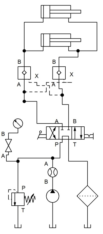
Like i did in the picture at the left(pilot operated check valve)?
Oh, so should switch the directional control valve (with the bypass position) to same valve but with float position?
valves_rdx1mi.jpg

And keep the unloader valve at the left that i have alread in my picture? Should i then set the airfilter before the unloader, and delete the entire right line(with filter)?.

What would be the main advantages to use 2 x single-acting cylinders instead of double-acting? To save energy?
 
The symbol to the left of the cylinders is a piloted relief valve and a check valve. See this link for a pilot operated check valve
The directional valve is fine with the open center center position. My suggestion for the pump unloader valve is not necessary.

Keep the system relief valve to the left of the directional control valve.

Ted
 
hydtools said:
The symbol to the left of the cylinders is a piloted relief valve and a check valve. See this link for a pilot operated check valve The directional valve is fine with the open center center position. My suggestion for the pump unloader valve is not necessary.
Keep the system relief valve to the left of the directional control valve.

Hi Ted!
I made a small adjustment to go with the relief valves you were suggested.
Is this a more correctly drawn system?
Would this work?
test1_zrwghm.jpg


Thanks again for your valuable inputs!
 
Hi again!
I have made another adjustment.
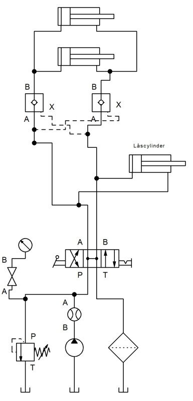
I did place an third cylinder that should act like a lock for the door that going to be opened.
So when the door is down it will be locked with the third cylinder.
Then i want the two opening cylinders to NOT begin operating before the third cylinder is at it´s fully open position.

How can i make this possible?
I would guess i could do it hydraulic, mechanical and electrical. But i dont know how.
Thanks !
test2_nhrntw.jpg
 
Now you need a sequence valve before the lock cylinder to actuate it after the hatch cylinders stop. You may not need another sequence valve to actuate the hatch cylinders after the lock opens. The low load of opening the lock may cause that cylinder to actuate before there is enough pressure increase to operate the hatch cylinders.

On edit: The check valves will lock the cylinders and the door will not move. The separate lock seems redundant.

Ted
 
Status
Not open for further replies.

Part and Inventory Search

Sponsor