Eng-Tips is the largest engineering community on the Internet

Intelligent Work Forums for Engineering Professionals

difference between composite and multi segment pos tol in asme y14.5 2009 5

Status
Not open for further replies.

Gopinath K

Mechanical
Jul 5, 2023
13
0
0
IN
Hi All
Can any one explain exact difference between composite and multi-segment pos tolerance, is Multi segment used for refinement of uppersegment ?
in both lower segment controls orientation and feature relation then what is the difference and how to choose which one to use with same datums.
refer images from asme y 2009 and list the difference pls
image from fig 7.39a and 7.46 c
 
 https://files.engineering.com/getfile.aspx?folder=d1a254b5-0999-4a3c-8eda-8566d4e384be&file=composite_tol.PNG
Replies continue below

Recommended for you

B is not redundant. It is to make sure that simulator C is oriented to simulator A and located to simulator B and not just oriented to A.

In other words, it is to make sure that both segments are evaluated relative to the same datum reference frame.
 
PMARC:

STOP TAKING PARTS OF STATEMENTS OUT OF CONTEXT.

B in the LOWER SEGMENT is only there because the committee decided it needed to be there. That's it. They made up a rule that makes for a nonsense control in this case.
 
3DDave,

I am not sure why you have a problem with what I said.

What you just said in your last reply is incorrect or at least partially incorrect. B in the lower segment is not redundant - it does exactly what I described. I am just not sure the committee was fully aware why it needs to be there.
 
When only orientation is being controlled then location is not a valid function.

Since it is a composite control the orientation of C is already fixed in the upper segment.

All that is required in the lower segment is a list of references that control orientation. B does not.

 
In order for the lower segment requirement to be a refinement of the upper segment, both segments need to be evaluated in the same datum reference frame established from simulators A, B and C. This will only be possible if B stands before C in the lower segment. A|C(M) would be a different datum reference resulting in different part-to-simulators relationship than in A|B(M)|C(M).
 
That's an arbitrary rule. The datum orientations are already established in the upper segment. The refinement is by mentioning only the ones that apply.

Look - the choice was arbitrary and sometimes results in nonsense. There is no rule outside of Y14.5 that says how Y14.5 rules have to be made. That they choose a foolish consistency is great. The reference to B only functions to satisfy the arbitrary rule and not any functional reason.

If the rule was "drop references that do not affect orientation" in the lower segment then you would not be arguing it was required. See - it is possible. Oh, right, just not under the arbitrary rule that says "Keep redundant and ineffective references in place."

 
By applying this logic, one can question any rule given anywhere as long as it doesn't match one's belief.

If A|B|C stands in the upper segment and one wants to obtain a true refinement in the lower segment B cannot be skipped as long as C means something in the lower segment. If C didn't meant anything, then B and C could be skipped.
 
SeasonLee and All,

Question 1: The C reference is necessary, because B cannot constrain the w rotation on its own. I agree with 3DDave and Belanger that B cannot constrain the w rotation, because it is perpendicular to A.

Question 2: The reference to C as the tertiary datum feature in the FRTZF should not be removed.

I also agree with pmarc that the B reference in the FRTZF is not redundant. Yes, this means that some of Y14.5's statements are not correct. In 7.5.1 (b) (3) it states the following:

"In some instances the repeated datum feature references may not constrain any degrees of freedom; however, they are necessary to maintain the identical datum reference frame, such as datum feature B in the lower segment in Fig. 7-42."

I would say that this is incorrect. This is nothing new, I've probably said the same thing in various threads over the years. In the case of Figure 7-42, datum feature B in the FRTZF actually does participate in the constraint. |A|C(M)| in the FRTZF would not establish the same DRF as |A|B(M)|C(M)| in the FRTZF. It is relatively straightforward to make examples that show this. Just draw an as-produced part in which the C slot is skewed and doesn't point directly at the center of the B hole.

Y14.5 also describes the FRTZF constraints correctly. Unfortunately, this is in the figure and not in the text ;^/. In Figure 7-42 (a), the captions say "FRTZF is constrained in rotation to datum plane A, datum axis B and datum center plane C" and "rotation controlled by datum axis B and datum center plane C". Both B and C participate in the constraint of the w rotation - it isn't just C on its own. I would say that these captions are correct.

So we have indications in Y14.5 that B doesn't participate in the constraint, and indications that B does participate. They can't both be correct. The way that I've approached this is to try to think through the consequences of each interpretation. What set of things would have to be true in order for B to not participate in the constraint, and what other set of things would have to be true in order for B to participate in the constraint? What I have found is that the set of things that would make B participate in the constraint is much more workable and makes a lot of things fall into place very nicely.


Evan Janeshewski

Axymetrix Quality Engineering Inc.
 
"doesn't match one's belief." is different than "doesn't add information to the description"

It is not necessary to establish an independent DRF in the lower segment, it is required to be the opposite; the definition is that the upper DRF controls all the datum locations and orientations relative to the part and to each other.

C is already established in the upper segment and, by definition, no datum is redefined in the lower segment, so there is only a need to refer to the elements of the DRF established in the upper segment that apply; no wheel to reinvent.

The rule is not a functional rule - it is a rule for getting people to comply to the rule. C, in the lower segment is exactly the same C by location and orientation in the upper segment. B does not need to be there as it does not refine the orientation of anything in the lower segment.

At the least, the convention should be to strike out any reference that does not affect the orientation of the feature relating framework to the datum reference frame, making it explicit that this is an intentional choice of a functionally unnecessary reference.
 
3DDave,

You are missing the fact that part of the evaluation of a geometric callout is the establishment and analysis of the part-to-DRF relationship, not only the tolerance zone-to-DRF relationship.

A|B(M)|C(M) and A|C(M) result in two different part-to-DRF relationships, therefore in two different part-to-tolerance zone relationships.

To see this, skip MMB modifiers entirely and imagine that the actual part is almost perfectly perfect except the slot C is tilted within its position tolerance zone relative to A|B (this tolerance would be on the real drawing). Then relate this part to A|B|C first and then A|C. You will see the difference in how the FRTZF behaves in both cases relative to the part.
 
The datums are established, fixed, immutable in location and orientation, relative to the part, in the upper segment, for all segments.

That is the sole DRF for the entire composite tolerance. The part is not allowed to change position or orientation in the lower segment. It is not a comparison to a datum feature - in the lower segment it is a comparison to the datum as already established in the upper segment.

It is optional to ignore portions of that DRF in the lower segment. The question is - is it required to re-reference a datum that plays no part relative to the orientation of the feature relating frame to the already established DRF.

 
You cannot expect two different segments of a composite callout using two different DRFs (by different, I mean a case where the order of datums is not respected by the lower segment) to be inspected in the same DRF.

This is actually what the statement in the standard, that you called arbitrary rule, tries to say - the datum reference frame needs to be maintained in order to be able to use a composite tolerancing concept.
 
Hi All,

This is getting interesting ;^).

Dave, it sounds like your instincts are mostly correct on this. It would make sense to use the same DRF for both segments. But pmarc is correct that A|B|C and A|C would not result in the same DRF (relationship between the actual part and the coordinate system and tolerance zones).

I would say that the main root cause of the widespread difficulties with FRTZF's is in Y14.5's description of how the datum features work. in 7.5.1 (b) (2) it states the following:

"If datums are specified in a lower segment, they govern the rotation of the FRTZF relative to the datums and within the boundaries established and governed by the PLTZF."

There are (at least) two ways that this statement can be interpreted:

1) The datum features referenced in the lower segment govern rotation of the FRTZF because they only control rotational degrees of freedom. So the lower segment is essentially similar to a customized DRF.

2) The datum features govern rotation of the lower segment govern rotation of the FRTZF because the FRTZF is allowed to translate relative to the DRF. So the lower segment is essentially similar to an orientation tolerance.

From what I have seen, interpretation 1) is by far the most common (I have talked to many people about this, including Y14.5 members). However, when I follow the consequences of each interpretation, I find that interpretation 2) is far superior. The set of things that needs to be true makes very good sense - it just works. It properly explains difficult composite FRF examples such as Figure 7-42 (and why the B reference is necessary). Interpretation 1) is reasonably workable for simple examples involving orthogonal planar datum features, but leads to untenable consequences in other cases.

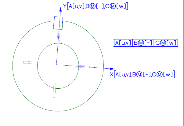
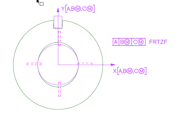
So where does that leave us with Figure 7-42? I would say that none of the customized DRF's properly capture the effect of the lower segment, because they can't. It's just not the same thing. The datum features in the lower segment constrain DOF's in exactly the same way as they do in the upper segment, and result in the same DRF. The upper segment controls location because the PLTZF does not translate relative to the DRF. The lower segment doesn't control location, because the FRTZF translates relative to the DRF. Figure 7-42 (a) shows this quite clearly.

Evan Janeshewski

Axymetrix Quality Engineering Inc.
 
So, this will be the correct way.

2023-08-11_120622_wvbcfx.jpg


Season
 
They aren't two (or more) DRFs in a composite tolerance. There is only one.

Leaving out datum entries in the lower segments, as is allowed for composite tolerances, eliminates the need for the feature relating frame to be oriented by the ones not included. In this case, there is a reference that cannot control orientation, but is still required by rule, not by function.

The composite tolerance is solely indicated by the single geometric control bridging multiple tolerance segments. The lower segments need have no datum references and therefore do not use any DRF in that case.

The top segment establishes the only DRF that is used by the entire composite tolerance. No re-interpretation of where the datums are or what their orientation is with respect to the part is allowed for the lower segments. All that the references affect in lower segments is the constraints on orientation of the feature relating frame relative to the already fixed DRF.

What you are repeating back is that there is a rule that accepts redundant and non-functional references in order to comply with the rule that requires accepting redundant and non-functional references.

It's circular reasoning, aka begging the question.

If you are right, each lower segment is a separate requirement and repeating the exact sequence in lower segments means that composite is sometimes the same as not composite.

So, follow the rule. It makes no sense and adds confusion, as SeasonLee revealed.
 
SeasonLee and All,

We really need the sketch, so here it is. This is the as-produced part that pmarc and I were describing, with the C slot that is skewed / off center relative to the B hole.

The customized DRF would result in this:

Int_1_zygdwv.png


I don't think this is what Y14.5 intended. The FRTZF is oriented to the center plane of the C slot, and B does nothing.

Here is how the lower segment would look, if we apply interpretation 2 from my earlier post:

Int_2_kbxmmt.png


I believe that this represents the intent of the lower segment properly. B and C both participate in constraining the w rotation. We need the B simulator to provide the axis about which the C clocks the part. Neither B nor C constrains the rotation on its own. After the DRF has been established, the FRTZF is allowed to translate relative to it - this is what makes the lower segment different from the upper segment.

Evan Janeshewski

Axymetrix Quality Engineering Inc.
 
So, each lower segment is a separate requirement? I'm kidding. They are because it is composite.

A rule is required to develop a simultaneous requirement to avoid being handled separately, even though the special case of a composite tolerance is to have only one DRF at all.

Seems like the problem is that the callout should be [A|B(M)|B(M)-C(M)] if B and C are required to restrain the last rotation.

However, that is the tertiary datum problem and this is a question of if there is one DRF in a composite tolerance or if each line is a separate requirement.

If they are separate, then why the restriction? What purpose does it serve? Let's look at the discussion transcripts/submitted use case evaluations. Which don't exist.
 
Status
Not open for further replies.
Back
Top