Eng-Tips is the largest engineering community on the Internet

Intelligent Work Forums for Engineering Professionals

difference between composite and multi segment pos tol in asme y14.5 2009 5

Status
Not open for further replies.

Gopinath K

Mechanical
Jul 5, 2023
13
0
0
IN
Hi All
Can any one explain exact difference between composite and multi-segment pos tolerance, is Multi segment used for refinement of uppersegment ?
in both lower segment controls orientation and feature relation then what is the difference and how to choose which one to use with same datums.
refer images from asme y 2009 and list the difference pls
image from fig 7.39a and 7.46 c
 
 https://files.engineering.com/getfile.aspx?folder=d1a254b5-0999-4a3c-8eda-8566d4e384be&file=composite_tol.PNG
Replies continue below

Recommended for you

3DDave said:
If you are right, each lower segment is a separate requirement

For what it's worth:
" Each complete horizontal segment in the feature control frames of Figs. 7-38 and 7-39 may be verified separately." (Y14.5-2009, 7.5.1 Composite Positional Tolerancing).
 
Evan said:
B and C both participate in constraining the w rotation.
I disagree. When the part is engaged with only the A and B simulators, the W rotation is free. Only when the C simulator is engaged, W is constrained.
That the sequence is meaningful is always true, but it doesn't make the B simulator take part in arresting clocking.
Consider it without the MMB modifiers for clarity of the principle that applies:
A,B,C is not like A,B-C.
 
"may be verified separately" doesn't say the datum requirements are separate.

The feature relating frames and related tolerance are necessarily separately verified.

Vague language with multiple interpretations not supported by the figures and examples.

Thanks Burunduk for again showing an example of the carelessness in crafting the standard.
 
3DDave,

There isn't much more to add by me in this discussion. I believe the second sketch made by Evan shows very nicely the idea I've been trying to convey.

If I had to make any comment about it, I would just say that it would be easier to see which simulator does what and why if this was all RMB case.
 
SeasonLee said:
So, this will be the correct way.

I say it is. You are this time right about the relevant degrees of freedom for each datum. But remember that the reason translations are not controlled for the FRTZF is because the tolerance zones can float in location (as a group), not because the datum feature simulators work somehow differently. Evan mentioned this recently in this thread and I also pointed this out in the past in this forum. As Evan also mentioned, it works like orientation tolerances do. The datum simulators immobilize the part as usual, but the tolerance zones of the "FRTZF" can move.
 
3DDave said:
"may be verified separately" doesn't say the datum requirements are separate.
If you evaluate each segment of the composite separately, you can set the part up for inspection on the datum-simulating fixture separately for each line.
So for the top segment you may get something along the lines of Evan's second picture, but with the zones aligned with the DRF,
And for the lower segment it could be Evan's first picture.
 
Burunduk - another case of taking a statement out of context. Your favorite argument tactic, but weak even for you.

When I specified that ONLY THE FEATURE RELATING FRAME AND RELATED TOLERANCE WAS VERIFIED SEPARATELY, I meant it.

Feel free to comment on what I wrote and refrain from creating your own fictional basis for response.
 
Burunduk,

I maintain that B participates in constraining the w rotation. When B is not referenced, the w rotation is constrained differently than it is when B is referenced - the diagrams show it. This means that B must take part in constraining the w rotation in some way. I don't think that

I'm also not suggesting that it should be A|B-C instead of A|B|C. That would result in a different DRF. In the case where there were no MMB modifiers, A|B-C would require that the B and C simulators somehow expand at equal rates to ensure that neither one took precedence over the other. I don't know how that would even work. The A|B|C reference is fine as is.

I think that what this does mean is that Y14.5's breakdown of degree of freedom constraints might be somewhat limited. We're not always able to step through the datum feature references one at a time, and identify all of the DOF's that each one really constrains. Maybe this is only true for rotational DOF's, so we see it when examining composite lower segments.

Here's another example that brings out the issues even more:

Plane-Hole-Hole_huteof.png


I'm wondering what you think of this. Is it a valid specification? If so, which feature(s) take part in constraining clocking?

Evan Janeshewski

Axymetrix Quality Engineering Inc.
 
3DDave said:
ONLY THE FEATURE RELATING FRAME AND RELATED TOLERANCE WAS VERIFIED SEPARATELY, I meant it
How can ONLY THE FEATURE RELATING FRAME BE VERIFIED SEPARATELY? Are you actually saying that the PATTERN LOCATING FRAME IS NOT VERIFIED SEPARATELY (OF THE FEATURE RELATING FRAME) HOWEVER THE FEATURE RELATING FRAME IS VERIFIED SRPARATELY OF THE PATTERN LOCATING FRAME?
 
Evan said:
I'm wondering what you think of this. Is it a valid specification? If so, which feature(s) take part in constraining clocking?
I say that only C constrains clocking because until the simulator for datum C is mated to the datum feature C hole, the DRF in which clocking is constrained is not established yet - the two planes that intersect at datum axis B can rotate freely.
 
Burunduk,

OK, we might have to agree to disagree on this. It might just be a wording problem - what each of us (and Y14.5) mean by the word "constrains". Perhaps you're making a distinction between the terms "constrains clocking" and "takes part in constraining clocking" that I wasn't making. I agree that the clocking is not constrained until hole C is engaged with its simulator, but I would also say that hole C could not constrain the degree of freedom on its own. If you're thinking that the feature that "finishes the job" is the one that constrains the degree of freedom, then okay.

Evan Janeshewski

Axymetrix Quality Engineering Inc.
 
Burunduk and 3DDave,

Y14.5's use of the word "separately" in 7.5.1 is another unfortunate example of loose terminology making things even more confusing. When they say that each segment in the FCF's in 7-38 and 7-39 may be verified separately, this is nothing to do with the concept of Separate Requirements from the DRF section. It would have been better to say that each segment may be verified independently. Wait, that might get confused with the Independency symbol. Perhaps "verified individually" might have been better. No, wait, that will get confused with the INDIVIDUALLY annotation which is similar to Separate Requirements. Let's just say that you can verify one segment without having to verify the other. ;^)

Regarding a simultaneous requirement (or lack thereof) between the upper and lower segments of a composite FCF, I don't think that we need to apply the rules any differently here. In most cases, the upper and lower segments would be separate requirements because they usually don't reference the exact same combination of datum features. But if they do, as in 7-42, then I would say a simultaneous requirement would apply.

Evan Janeshewski

Axymetrix Quality Engineering Inc.
 
There are three parts to a feature control frame composite callout.

The common geometric characteristic
The feature relating frame as established by dimensions between features
The optional datum reference frame as established by dimensions to and among datum features

Each segment of a composite tolerance has at least the first two, with the geometric characteristic being common and indicating that every same lettered datum reference in each segment is from the same, top level, datum reference frame.

Each feature relating frame is separately evaluated.

The PLTZF is a combination of the feature relating frame and the datum reference frame and is used as a basis for evaluating the top segment tolerance zone. It both locates and orients the feature relating frame to the part.

The FRTZF is a combination of the feature relating frame and, if there is any, the retained elements of the datum reference frame, and each is used as a basis for evaluating the relevant segment tolerance zone. It only orients the feature relating frame to the part.

Not the same datum feature separately evaluated; that happens just once. Just each feature relating frame.
 
Evan, it cannot be a refinement of a requirement if the basis for that refinement is allowed to change.

If it is allowed to change then the requirement for the order being the same, but not all the entries, seems like a needless restriction.
 
The FRTZF is not related to "retained elements of the datum reference frame" but to the datum reference frame established by the datum references in that same segment. The principal difference between the top segment and any subsequent segment of the composite tolerance is in which degrees of freedom are considered for constraining the tolerance zones to each datum reference frame. It is only rotational DOF for all segments other than the top.
Each lower segment is a refinement of the controls already established by the segments above it - that's why you need the order maintained and no skipping of the secondary reference if the tertiary is kept.
 
Evan,
We may be agreeing more than disagreeing in essence.
Although yes, I do think that the datum feature that "finishes the job" of applying a constraint is the one that officially constrains whatever degree of freedom is considered, but I think it is so in every single case of any datum reference frame of more than one datum being used. The preceding datum references always "lay the foundation" for the constraints applied by the subsequent references.

I'm no committee member or a well known GD&T trainer, but I do my best to explain the concepts to my coworkers according to my best understanding, and what I always tell is that every datum, whether it is a point, a line, a plane or a combination of them, is connecting the part in a way to one or more planes and at least two axes of the DRF. You can't continue connecting the part to the DRF by secondary and tertiary references before the initial connection is made by the primary or primary and secondary references.

The case of the secondary cylinder datum axis and the tertiary slot center plane being discussed here are no exception. A simpler example for the same principle is just two planar datum features referenced as primary and secondary. The primary may establish the connection to the XY plane and constrain Z, u, and v. The secondary then constrains X and w - but it couldn't do so unless the part was previously aligned to the XY plane!

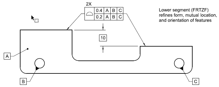
Now with that in mind if we examine the primary plane, secondary axis, tertiary center plane example - the tertiary reference can't constrain rotation about the secondary axis before the connection of the part to that axis is established by the primary and secondary datum references. But that's not unique and doesn't mean that the rotation is constrained by both the bore and slot and their simulators - only the slot and the simulator tab do that after the ground for it is ready.

Note that the datum feature and simulator B do constrain that part in translational degrees of freedom - but they do not constrain the FRTZF which can translate relative to the applicable DRF by floating!
 
A star for Burunduk for his last two replies as they, in my opinion, summarize the two topics - 1) the need for B in the composite FCF and 2) the rotation constraint by C - very well.
 
Burunduk,

Your statement in bold in the last post sums it up nicely. Once I started thinking of composite FCF's in this way, then things really fell into place. Before that, I had been struggling to visualize how the datum feature simulators would have to behave in order to only constrain rotational DOF's. For counter-intuitive examples like 7-42 and even for simpler examples involving planar datum features. It seemed that special "translatable" or non-basic simulators would be needed, but these were never described or even mentioned. The fact that the figures in Y14.5 for composite FCF's never show the simulators didn't help - they sometimes show the datums and DRF but not how they were established. It was so much simpler to be able to say that the datum features in the lower segment constrain DOF's just like they do in the upper segment, and it's the FRTZF that translates.

I believe that customized DRF's require translatable or rotatable simulators, but that's a whole other story.

Evan Janeshewski

Axymetrix Quality Engineering Inc.
 
The FRTZF is not related to "retained elements of the datum reference frame" but to the datum reference frame established by the datum references in that same segment.

The FRTZF has no requirement for any datum references, so this is a flawed statement. If you had parroted what I wrote you would have been correct.

The principal difference between the top segment and any subsequent segment of the composite tolerance is in which degrees of freedom are considered for constraining the tolerance zones to each datum reference frame.

So the DRFs can be entirely different? That doesn't seem in the spirit of the composite rules.

It is only rotational DOF for all segments other than the top.
Each lower segment is a refinement of the controls already established by the segments above it - that's why you need the order maintained and no skipping of the secondary reference if the tertiary is kept.

But if the datum reference frame is already established then there is no need for that.

The argument once again devolves into parroting the standard without analysis.
 
Status
Not open for further replies.
Back
Top