ChorasDen said:
I've never taken the time to read through the attachment, but I've saved it in the hope that I will read it one of these days.
I began reading it today, and I can't say that I agree with one of the main concepts it uses which is likely the point of the whole document (i.e. to design a true folded plate).
I suppose it's due to the lack of structural ridge beam, but the document suggests that loading at the ridge lends to thrust and is taken out through the vertical plane of the diaphragm and resolved to the end walls. My understanding in how structures really perform is, if this thrust is present then it's likely the ridge is deflecting. This just doesn't see acceptable to me when we can easily use a collar/rafter tie or a structural ridge beam to alleviate this problem.
So, for the hour that I spent reading the document, I haven't come away with any more insight on how our traditional gable diaphragms work.
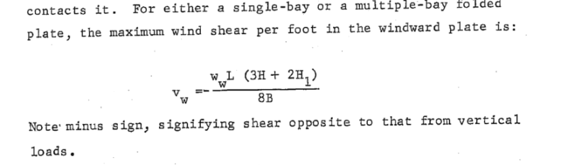
They provided this formula for wind shear, but I don't quite understand it.
_______________________________________________________________________________________________________________________________________________
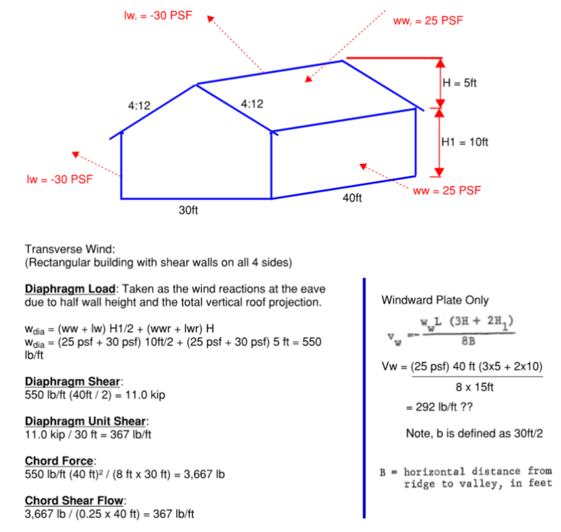
[highlight #FCE94F]I've worked out a scenario for a roof diaphragm where the entire roof acts as one unit. The calculation of the "windward plate" is shown for comparison:[/highlight]
Note in the example below, I chose a windward roof pressure and leeward roof pressure that contribute to the same overall direction.
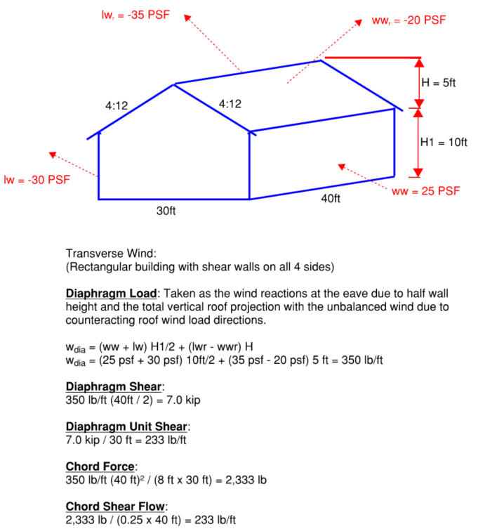
[highlight #FCE94F]For completeness, I did the same scenario for wind loading that represents a more typical scenario where the windward roof and leeward roof are in opposing directions. I'm providing this to also get your opinion on it.[/highlight]
What I've attempted to understand here is HOW we assume these two planes act together. What really trips me up is that I think the proper way to handle the 1/2 projected wall height is to take the lateral load coming from the wall, and find the vector that pushes load into the plane of the diaphragm.
If you were to only consider the windward wall from either example above, treating the plane of the roof as a two-force member:
(25 PSF x 5 ft) / cos (18.43°) = 131.75 lb/ft (in lieu of 125 lb/ft)
This would give you a load that travelled parallel to the plane of the roof.
The other force component would act vertically down on the projected horizontal plane of the roof:
131.75 x sin (18.43°) = 41.65 lb/ft (Vertical Y)
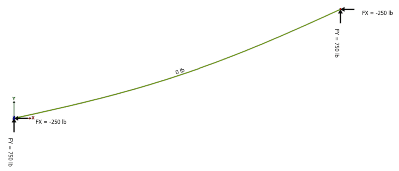
Now for the wind that is normal to the roof (i.e. roof wind load), I understand there is no axial force in the plane of the roof due to wind (therefore you cannot say that wind is pushing parallel into the plane of the roof). But based on the vertical projection of the roof, there is a lateral reaction at the eave and ridge. You can solve that with a FBD, but I don't understand the mechanism behind how the diaphragm "feels" this shear load transfer in the plane of the roof since the wind component is normal to the roof.
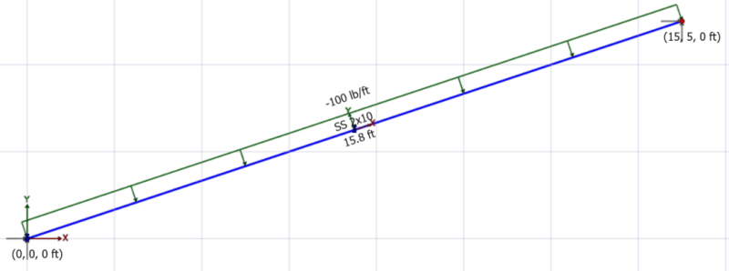
Linear load normal to the plane of the roof (represents wind load)
Axial load and reactions at the eave and ridge:
Note there is no axial which to me would have been the force parallel to the plane of the roof. Yet statics has to be in equilibrium so we have overall horizontal reactions.
I hope I've explained my confusion well enough and that I haven't ended up losing any credit points in the process. I return to this question every couple years and end up just accepting normal practice because it's become so time consuming. But there has to be an explanation that I'm not seeing.
KootK, I know we've discussed ad nauseam and you mentioned the accounting is so involved most probably move past it. Sorry to re-hash old discussions.
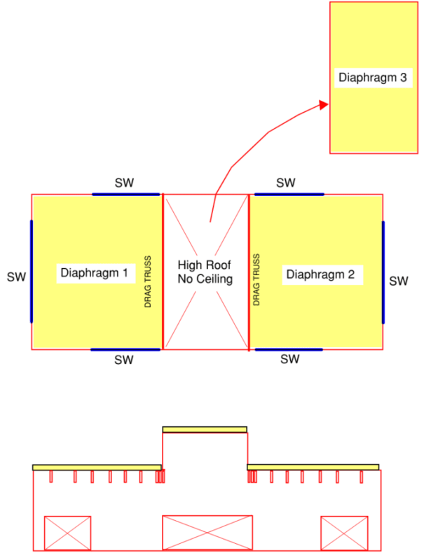
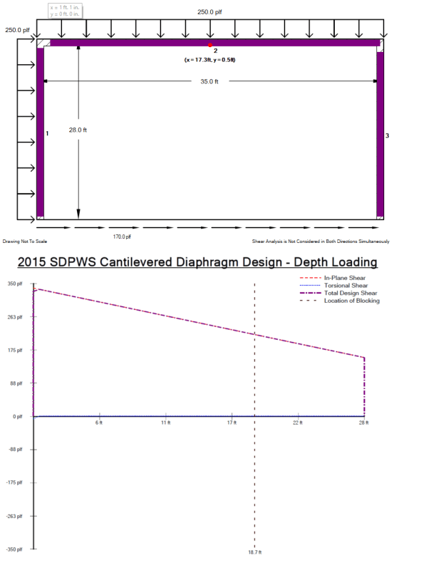
I know that some of you understand the time commitment to just ask the question in the first place (examples, images, descriptions, etc.) I wouldn't be doing this if I didn't feel the need to get this one solved.