Continue to Site

Eng-Tips is the largest engineering community on the Internet

Intelligent Work Forums for Engineering Professionals

  • Congratulations KootK on being selected by the Eng-Tips community for having the most helpful posts in the forums last week. Way to Go!

Eccentric load on weld groups 2

Status
Not open for further replies.

HanStrulo

Civil/Environmental
Apr 16, 2021
117
HI Everyone,

For anyone familiar with both AISC and CISC. I have a question.

Table 8-4 of AISC gives the coefficient C for eccentrically loaded weld groups (out of plan force and at an angle of 45 degrees).

I looked in CISC and could not find a similar table. The closest i could find was table 3-27 but it's for in-plan eccentric vertical load).

Did i miss something? what is recommended to do in this case?

Thanks
 
Replies continue below

Recommended for you

HanStrulo said:
For the channel flange, should I check it against flange yielding, crippling? these are usually done for the web because they are usually loaded on the flange, but in this case, the channel is loaded on the web.

No sweat, good on you for setting your work down for the weekend.

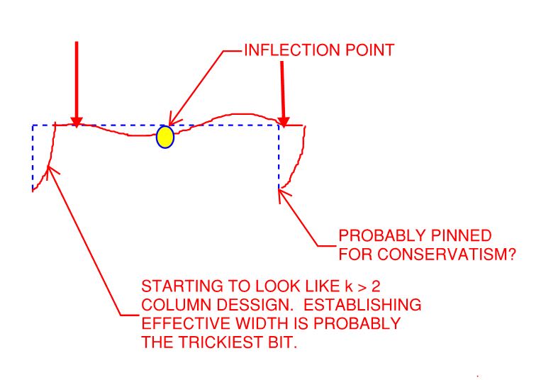
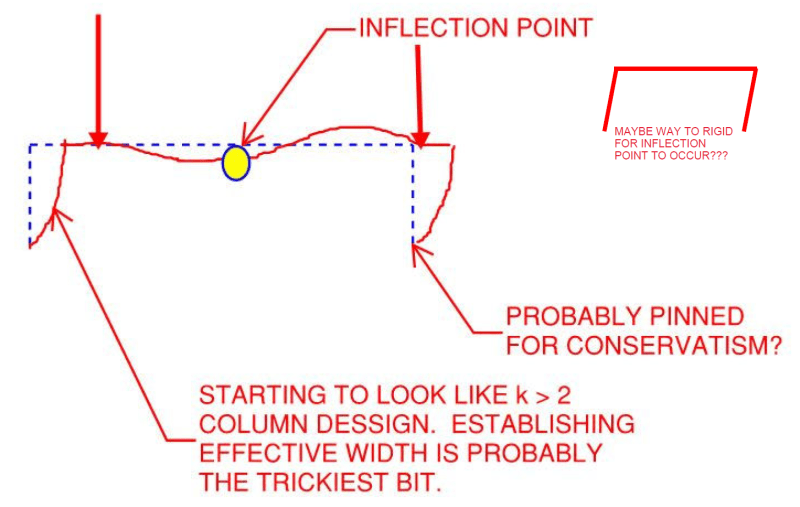
Yes, I agree with your statement quoted above. It suggests a rather punitive buckling model, however, as shown below.

MGaMart suggested some additional stiffeners a while back. While I agree that those are likely unusual for such an application, and thus prone to raising eyebrows one wants to keep lowered, it's interesting to note that they would do an amazing job of restraining this particular buckling mode.

C01_qgduuq.jpg
 
@ Kootk

I checked for crippling and yielding as per the code and it turned out to be ok. I used a very short bearing length to be conservative.

Thanks alot for the guided help you provided.
 
or possibly...
image_kbmyzj.png


Rather than think climate change and the corona virus as science, think of it as the wrath of God. Feel any better?

-Dik
 
@Hanstrulo

Is this analysis your doing based in the US code or in Canadian code (i.e. which code are you trying to stick to in conducting this analysis)? Crippling is approached rather differently by each code (why that is the case baffles me to this day). I suspect you are using the AISC spec for the crippling check since it utilizes bearing length in its equation. Good to hear it passes but I'm curious as to what bearing length you applied. Very conservatively, you could have used bearing length = angle thickness, but that would likely be short-changing yourself to go that small. I think the bearing length would need to be rationalized by the effective length established at the angle-to-channel interface. Utilizing something comparable to the Whitmore section may be suitable in determining how far the load disperses before reaching the channel flanges, thereby giving you a better sense of what bearing length should be applied for yielding, crippling, and buckling checks.

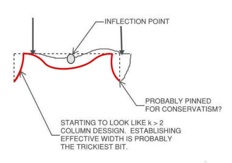
This is my take on the buckling shape. The position of the load and the fact that you are dealing with tapered flanges I think would naturally induce this deformation pattern across the channel cross section. The web would deflect highest at its midspan and would want to kick the toes of the flanges out (away from its center of gravity). Ultimately, it would come back to likely using a K=2 value, but since the translation of the channel web-to-flange corner is semi-restrained by its adjacent corner (i.e. self-limited translation), you may be able to argue a slightly smaller K value in your analysis. Safer though to just use K=2.

C01_qgduuq_s5j0j3.jpg
 
Status
Not open for further replies.

Part and Inventory Search

Sponsor