Eng-Tips is the largest engineering community on the Internet

Intelligent Work Forums for Engineering Professionals

  • Congratulations waross on being selected by the Eng-Tips community for having the most helpful posts in the forums last week. Way to Go!

Elevator Machine Reaction Forces

Status
Not open for further replies.

mikek396

Mechanical
May 28, 2022
28
US
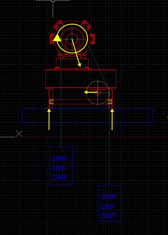
Here is a typical block up elevator machine arrangement with car and counterweight. The car is supported by cables that run over the driving machine sheave, onto a deflector sheave (frictionless) and then down to the counterweight. I am trying to find the most accurate way to analyze the reaction forces at the base of the block up assembly (red) acting on the supporting beam (blue). Obviously the car and counterweight cause tension in the cables that travel over both sheaves - where should this tension be applied? A coworker says I can simply idealize the cable tension as a point load directly on the blue beam at the locations they pass the supporting beam.

My instinct says this isnt the proper way to analyze this. I think I need to start by figuring out the reaction forces of the machine and deflector sheave onto the red beam they are both mounted to. However, I run into the problem that the cable tension is unequal from the car side to the counterweight side. I believe the cable tension on either side of the deflector sheave is equal, but the angle of the rope causes a force downward and towards the drive sheave on the deflector. How should I be analyzing the drive sheave? Am I overthinking this?
 
 https://files.engineering.com/getfile.aspx?folder=c2734bd6-f32e-4485-bac0-e46999812d2b&file=image.png
Replies continue below

Recommended for you

The reactions at each mounting foot are the sums of the moments about the opposite foot divided by the distance to the other foot.

That includes the loads from the cables and the weight of the motor/gearbox and the weight of the frame.

The other forces are internal forces and don't affect the load on the beam.
 
Isn't this like a first year statics problem that can be solved with a simple FBD, or am I missing something here?


This is a free body diagram of the red thing, cables included. Red thing has forces 1, 2, and 5 acting on it (weight), and there are reactions forces and moments where the red thing contacts the rest of the world (blue beam) at 3 and 4 (I generalized in my sketch. Some of these are equal to 0).

Write your equilibrium equations and solve for the unknowns.


I think I need to start by figuring out the reaction forces of the machine and deflector sheave onto the red beam they are both mounted to
Why? The machine as a whole sits on the blue beam. Internal forces throughout the machine have nothing to do with the contact point between the machine and the beam.
If the two of us sit inside the car and we start arm wrestling, our arms don't add anything to the reactions between the wheels and the road.
 
Hi mikek396

I agree with your coworker basically if you take moments about one of the frame feet (in red) and divide it by the distance to the other foot then that will yield the reaction on that foot so for example

2;500 x X1 + 3500 x X2 = R1
—————————————————————-
X3

X3 = distance between frame legs

“Do not worry about your problems with mathematics, I assure you mine are far greater.” Albert Einstein
 
"Am I overthinking this?" ... yes.

the loads between the red and the blue don't change with hoe the loads are applied, or what "conniptions" or tortious internal loadpaths therea are.
All that matters, to the external reactions is the force and it's line of action.

I expect there's some toothed belt and brake in the system to balance the 2500 lbs load and 3500 lbs counterweight ?
Where does the belt tension change from 2500 lbs to 3500 lbs ?

another day in paradise, or is paradise one day closer ?
 
You could get a reaction torque on the mount from the motor itself, as it runs the car up and down; this potentially puts wear and tear on the mounts; I used to have very torquey engine that had a habit of breaking its motor mounts, simply from the torque reaction.

TTFN (ta ta for now)
I can do absolutely anything. I'm an expert! faq731-376 forum1529 Entire Forum list
 
yes, you need to include motor torque, as this is another external load on the the red shape. And I think there is always some torque, balancing the load and the counterweight.

another day in paradise, or is paradise one day closer ?
 
@rb1957 correct, there is always some torque on the motor as the car and counterweight are very rarely balanced. This is a steel cable system with the cables running over the drive sheave which is where the cable tension will change from 2500 - 3500. Is this friction force something that I need to be including in my analysis, or can I simply say the torque is the 1000 lb delta x sheave diameter and then resolve this torque into a force couple at the machine feet?
 
torque = 1000 lbs * sheave radius, no?

yes, red would apply a couple to blue due to this torque.

but is this force applied laterally ?
so then there'd be a lateral force between red and blue, no?

my thought experiment was "what would happen to the cable if the motor wasn't there ?" obviously, the counterweight would run away

another day in paradise, or is paradise one day closer ?
 
torque = 1000 lbs * sheave radius, no? - this is what I meant (difference btw car and cwt * radius)

where do you see a lateral force coming into play between red and blue? The only lateral force I can think of here is compression acting on the red beam between drive sheave and deflector sheave (which would be an internal force)
 
"can I simply say the torque is the 1000 lb delta x sheave diameter"

The lateral force ... yeah, this probably needs some thought. I think the motor is "only" applying torque to the red body. It is applying a force to the cable, changing the tension in the cable, but I think this is being reacted by the motor attachment to the red body (so that "all" the red body sees from the motor is the torque

another day in paradise, or is paradise one day closer ?
 
"A coworker says I can simply idealize the cable tension as a point load directly on the blue beam at the locations they pass the supporting beam."

This is wrong, and it'll result in a relatively large amount of error in the reaction moments at the feet of the red structure. Whether that error makes the design more or less conservative is an unknown- you'd have to do the math on both scenarios to know, which to me means you might as well just do the math on the accurate version.

If you're modeling the pulley on the right as frictionless, with no brake, and the structure and beam as infinitely stiff, these are the only real forces applied to the red structure:

Capture_yssego.jpg


You need to resolve the vertical component of that force vector which passes through the center of the motor sheave, the moment applied to the motor sheave, and the normal force due to the weight of the red structure in order to arrive at the reactions at the beam.
 
won't the two loads you show (from the motor sheave and the other lateral force) sum to the two weights (the load and the counter weight) at their lines of action ?

so the external loads on the red are the weights and the motor torque ?

or is the motor torque (added by me !?) a red herring ? the motor torque is reacted by the couple between the load applied to the cable and the reaction applied to the red body ?
and then not an external load ...

another day in paradise, or is paradise one day closer ?
 
Hi mikek396

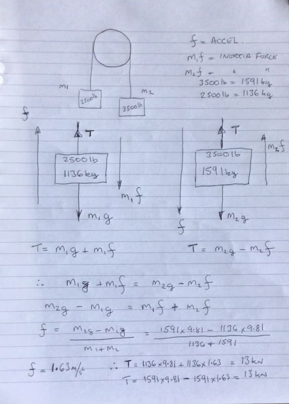
If I ignore any inertia and friction of the sheaves and consider the two masses as being placed over a sheave then you can calculate the tension in the cable assuming the masses are in free fall, whilst this is not quite the situation you have it might help, that said I guess when you throw in torque of the motor in it will change slightly however I post my cable tension solution below. The tension on either side of the sheave in this case is equal and if you workout the resultant force on the top sheave resolving the cable tension and it direction you can apply it as a point load onto the blue beam through the feet of the red support structure.
708FA5E4-969C-4D4A-99AB-AA0289B7D639_nwkugx.jpg


“Do not worry about your problems with mathematics, I assure you mine are far greater.” Albert Einstein
 
but I don't think it works like that (I'm not in the elevator business, last time I looked at this type of problem was back at uni).

Yes, that is how to balance the load and the counterweight, in the absence of any other control. But I'm sure the motor is preventing the counterweight from falling ... I mean you don't see the elevator counterweight changing to match the load nor the required motion of the car.

I'm thinking the original co-worker is correct, you only need to consider the external loads to determine the loads from the red to the blue (and from teh blue to the "rest of the world"). I think motor torque is a red herring, as the motor applies load to the cable and reactions to this load to the red body.

another day in paradise, or is paradise one day closer ?
 
Hi rb1957

Well we don’t have any info on the motor, I suspect there is a brake on the system when not in use and whilst it’s stationary the cable tension won’t play a part in the calculation but it applies only when in motion and yes I stated in my post that things would change when the motor torque comes into play. The motor though would only act to supply the difference in torques and provide a controlled lift or descent of the cage or carriage.
I also think his coworker was correct or at least close enough for design purposes which I mentioned in my earlier post.

“Do not worry about your problems with mathematics, I assure you mine are far greater.” Albert Einstein
 
rb1957 said:
the motor applies load to the cable and reactions to this load to the red body.

Those loads don't just disappear - they have to make it down to the feet to be resolved.

In practical terms, the loads don't create a moment sufficient for overturning (ie, the bolts holding the red feet to the blue beam are never going to see tension) but the motor torque does affect the magnitude of the two reactions. In either a dynamic or static analysis of this system the motor torque cannot be ignored. We don't know the size of the motor spool - but if it's a 24" spool (a common-ish size for elevator gear) that is a 1000 ft/lb load at rest with the car not loaded. That's significant.
 
that was my initial line of thought ... the motor must be applying some load to the cable, to keep it in balance, so we know the torque of the motor (1000 lbs x the sheave radius). But then I thought, wait on, the motor is applying an opposite torque to the red body (where the motor is attached) so now I think the motor doesn't affect the red/blue interface loads. But I'm willing to be wrong ... as I said, the last time I had to think about something like this was uni ... literally a lifetime ago !

another day in paradise, or is paradise one day closer ?
 
Hi rb1957

There must be something stopping the the weights from rotating under their own weight but when the motor is not energised I would assume some kind of brake. The motor, sheaves and cable etc when the thing is stationary is just dead weight which will ultimately be carried by the blue beam, however in operation we have the motor torque to factor in and any acceleration of the 2500lb or 3500lb weights will create additional tension in the cable which will be taken through the feet of the red beam onto the blue beam. Statically you could resolve the cable forces due to the two weights through the top sheave and get a resultant force and direction at some angle to the vertical and apply that on to the blue beam via the red feet, however don’t see that being much if any different from taking moments about the red frame foot as I previously posted.
Without any more information regarding mass, inertias and torque from the motor it’s hard to take it much further.

“Do not worry about your problems with mathematics, I assure you mine are far greater.” Albert Einstein
 
desertfox said:
don’t see that being much if any different from taking moments about the red frame foot as I previously posted.

It's different because the forces are not truly applied at the locations where the cables hang next to the beam- they are applied through the centerline of the shaft on which the pulleys live. That changes the values of the moments.

As I said earlier - to know which scenario is the more conservative, you would need resolve all forces and calculate reactions for both. If you're going to do that, you might as well save time and just calculate the one that's right.
 
Status
Not open for further replies.

Part and Inventory Search

Sponsor

Back
Top