Eng-Tips is the largest engineering community on the Internet

Intelligent Work Forums for Engineering Professionals

  • Congratulations waross on being selected by the Eng-Tips community for having the most helpful posts in the forums last week. Way to Go!

Elevator Machine Reaction Forces

Status
Not open for further replies.

mikek396

Mechanical
May 28, 2022
28
US
Here is a typical block up elevator machine arrangement with car and counterweight. The car is supported by cables that run over the driving machine sheave, onto a deflector sheave (frictionless) and then down to the counterweight. I am trying to find the most accurate way to analyze the reaction forces at the base of the block up assembly (red) acting on the supporting beam (blue). Obviously the car and counterweight cause tension in the cables that travel over both sheaves - where should this tension be applied? A coworker says I can simply idealize the cable tension as a point load directly on the blue beam at the locations they pass the supporting beam.

My instinct says this isnt the proper way to analyze this. I think I need to start by figuring out the reaction forces of the machine and deflector sheave onto the red beam they are both mounted to. However, I run into the problem that the cable tension is unequal from the car side to the counterweight side. I believe the cable tension on either side of the deflector sheave is equal, but the angle of the rope causes a force downward and towards the drive sheave on the deflector. How should I be analyzing the drive sheave? Am I overthinking this?
 
 https://files.engineering.com/getfile.aspx?folder=c2734bd6-f32e-4485-bac0-e46999812d2b&file=image.png
Replies continue below

Recommended for you

I guess I made the implicit assumption that the car was static.

Assuming this (static car), I would calc the interface loads red/blue and blue/"rest of the world" from the two loads shown, as suggested by co-worker. I think everything within the red body is "irrelevant" to the overall load balance.

another day in paradise, or is paradise one day closer ?
 
Hi rb1957

That was my assumption also and I fully agree with you, in fact if time permits I might assume some dimensions and calculate resolving through the top sheave and the way the coworker suggested.

“Do not worry about your problems with mathematics, I assure you mine are far greater.” Albert Einstein
 
Hi swinneyGG

If I take moments about the red feet I will get the reactions at the red feet, you can take moments about any point in a structure.

“Do not worry about your problems with mathematics, I assure you mine are far greater.” Albert Einstein
 
desertfox said:
If I take moments about the red feet I will get the reactions at the red feet, you can take moments about any point in a structure.

Right... but if the vertical loads move relative to the feet, the moments change. The vertical loads are not applied at the point where the wire rope hangs next to the beam; they are applied at the shaft on which the sheave lives. That changes the distance and thus the moment applied by each force, and it's also why you can't ignore the torque applied by the brake which is holding this whole system in a static position.
 
if the loads move vertically, (ie start at height H1, move then static at height H2) then no change to external reactions.

there would be a change during motion, when the weights accelerate.

another day in paradise, or is paradise one day closer ?
 
I'm not talking vertically. I'm talking horizontally - ie the distance between where the load is applied and where the reaction force is applied by the beam, in the x axis.

The loads from anything hanging from those cables are not applied at the location where the cable crosses the beam. They are applied to the shaft carrying the sheave.
 
well then, yes. the "load" as I speak of it is the load vector, magnitude and location.

"The loads from anything hanging from those cables are not applied at the location where the cable crosses the beam. They are applied to the shaft carrying the sheave." ... um, sorry I disagree. The load's line of action determines the external reactions, not how the load interfaces with the innards of the red body.

another day in paradise, or is paradise one day closer ?
 
I agree with this part:

rb1957 said:
The load's line of action determines the external reactions

But the line of action is through the center of the shaft.

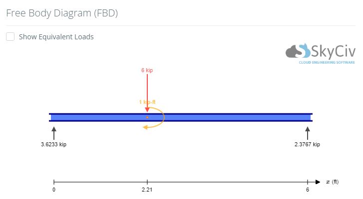
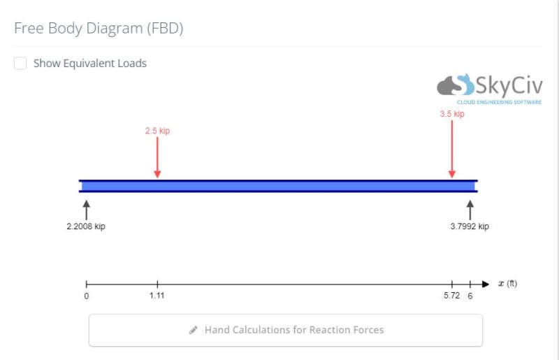
You're saying that this arrangement of forces, which represents the real world:

fbd2_mjvpbz.jpg


Is accurately modeled by this arrangement of forces:

fbd1_ljqmdy.jpg


That just isn't true. Sorry. The reactions aren't even close.
 
3.5*(5.72-2.21)+2.5*(1.11-2.21) = 12.285-2.75 = 9.535 .NE. 1 ... the scenarios "aren't even close".

another day in paradise, or is paradise one day closer ?
 
apply 3.5 load at 3.28 for a net moment of 1

another day in paradise, or is paradise one day closer ?
 
rb1957 said:
3.5*(5.72-2.21)+2.5*(1.11-2.21) = 12.285-2.75 = 9.535 .NE. 1 ... the scenarios "aren't even close".

Uhhh... yeah. Exactly. The 1 kip/ft moment is the actual load applied to the red frame by the brake torque holding the loads in place (assuming a 24" traction sheave diameter... which I did). The imaginary moment you calculated above has nothing to do with anything.
 
@swinnyGG ... your two loading examples are not the same, so their reactions are not the same.

I think the correct loading is scenario 2. You can think otherwise, it's a free world.

The line of action of the loads is not through the sheave, but is along the weight vectors (since the load is weight).
I think scenario 1 should include the load at the idler ... the loads on these two (the main load on the sheave and a secondary load on the idler) should be (must be) equivalent to the weights applied. This is not a choice. The loading in scenario 1, as rational as it appears, is not equivalent to the applied weights.

another day in paradise, or is paradise one day closer ?
 
The load is not 'weight' - it's cable tension.

If the cables were anchored to the ground at each end and the cable stretched the correct amount, there would still be tension.

And that tension would still be applied to pulleys.

Which would still apply any loads they carry through their shafts and bearings, not through an imaginary vertical line tangent to their OD.

You're right - it's a free world - so if you want to give incorrect advice, you're welcome to. But there is exactly 1 correct solution to OP's problem statement, and I've covered it already.

OP stated in his original problem statement that he's considering the deflector sheave as frictionless; by convention in machine design, frictionless sheaves can only apply loads normal to and in line with their shafts. In this case that means the vertical load which would exist on that sheave in the real world is replaced with a zero. The horizontal load applied to that sheave is resolved internally in the red structure; the only remaining vertical force is the load through the shaft of the traction sheave.

You can't always apply dynamics 101 assumptions about problem solving to the real world. Easy example from this specific problem is that in 101 level engineering classes we are all taught than for any cable passing over a pulley, tension in both legs will always be exactly the same. In the real world, and in this specific problem, that isn't true because friction exists.
 
Hi all
I have produced a simple example to try and resolve our differences of opinion about taking moments about pulley centres or at the line of action of the attached masses.
Clearly the example had to be in equilibrium for it to work as must be the original problem set by the OP. Anyway I ended with the result being the same outcome for both scenarios.

“Do not worry about your problems with mathematics, I assure you mine are far greater.” Albert Einstein
 
 https://files.engineering.com/getfile.aspx?folder=09fe2800-aa2c-49c4-828e-1d58cd0f190e&file=7B7CB3BF-AD62-4647-9371-CC6C44E787AA.jpeg
In your test case, where you take the moments works out to be the same because:

1) The locations of the moments, pulley centers, pulley diameters, etc relative to the support locations are all symmetrical.

2) The loads you've used are balanced, which means in the second scenario there is no applied moment required to hold the loads in place.

The original problem statement is asymmetrical, and there's an additional moment applied to prevent movement of the load.

 
SwinneyGG said:
[I'm not talking vertically. I'm talking horizontally - ie the distance between where the load is applied and where the reaction force is applied by the beam, in the x axis.

The loads from anything hanging from those cables are not applied at the location where the cable crosses the beam. They are applied to the shaft carrying the sheave.]

I was referring to your post copied above in relation to the loads being moved from the tangents of the pulleys to the axle pulley centres. I agree that the loads in the OP’s original question need an additional moment to prevent movement of the weights but we have no idea other than a brake of some description how this is done.

“Do not worry about your problems with mathematics, I assure you mine are far greater.” Albert Einstein
 
I get that.

The point I'm making in my post from earlier this morning is that applying the forces at the centers of the pulleys is only exactly the same as at the tangent to the pulleys because, in your example, the force locations are perfectly symmetrical.

If you us an asymmetrical example, the two scenarios are no longer the same.
 
weight, load, tension ... they all equivalent in a static case.

If there was a black box around the structure, and all you saw were the two weights (and the ropes attaching them to the black box) and the blue beam protruding beyond the black box (supporting the structure to "the rest of the world), how would you calculate the reactions at the end of the blue beam ? Two applied forces, two reactions ... simple.
Then look inside the black box. Each time you simplify the load, say remove the cable and have the loads applied at the pully centers, then your loading must be exactly equivalent to the earlier loads ... same direct load, same moment about the same point. By moving the direct load to the sheave you are ignoring the load on the idler, which is mostly horizontal so the load at the sheave also has a horizontal component (small though it may be) and here is the couple (moment) you've lost.

another day in paradise, or is paradise one day closer ?
 
I'm picturing a case where instead of one, there are two idler pulleys. The rope, wrapped around 180 degrees of the motor pulley, leaves the motor pulley so that the two ends go horizontally, one end for each, over the top of the idlers before hanging down.

Now the load on the motor pulley is exactly horizontal and the idlers, being frictionless, would have no vertical reactions, meaning that the tension in the cables does not pull down on the structure.

This seems unreasonable.
 
I don't get what you're saying.

ok, have two idlers ... the cable goes straight down from the main sheave, yes?
then a new idler directs the cable (horizontally towards the existing idler ... cable turns through 90deg, reaction is inclined at 45deg.
then the existing idler takes the (now) horizontal cable and turns it through 90 deg so the cable is now down ... again reaction is inclined 45deg.
These two reactions are not co-linear, creating a couple that equals the moment due to the cwt cable being translated horizontally from the sheave.

another day in paradise, or is paradise one day closer ?
 
Status
Not open for further replies.

Part and Inventory Search

Sponsor

Back
Top