Eng-Tips is the largest engineering community on the Internet

Intelligent Work Forums for Engineering Professionals

  • Congratulations waross on being selected by the Eng-Tips community for having the most helpful posts in the forums last week. Way to Go!

Elevator Machine Reaction Forces

Status
Not open for further replies.

mikek396

Mechanical
May 28, 2022
28
US
Here is a typical block up elevator machine arrangement with car and counterweight. The car is supported by cables that run over the driving machine sheave, onto a deflector sheave (frictionless) and then down to the counterweight. I am trying to find the most accurate way to analyze the reaction forces at the base of the block up assembly (red) acting on the supporting beam (blue). Obviously the car and counterweight cause tension in the cables that travel over both sheaves - where should this tension be applied? A coworker says I can simply idealize the cable tension as a point load directly on the blue beam at the locations they pass the supporting beam.

My instinct says this isnt the proper way to analyze this. I think I need to start by figuring out the reaction forces of the machine and deflector sheave onto the red beam they are both mounted to. However, I run into the problem that the cable tension is unequal from the car side to the counterweight side. I believe the cable tension on either side of the deflector sheave is equal, but the angle of the rope causes a force downward and towards the drive sheave on the deflector. How should I be analyzing the drive sheave? Am I overthinking this?
 
 https://files.engineering.com/getfile.aspx?folder=c2734bd6-f32e-4485-bac0-e46999812d2b&file=image.png
Replies continue below

Recommended for you

rb1957 said:
Then look inside the black box. Each time you simplify the load

That's the point- when you remove the black box, you aren't simplifying anything. You are gaining information, and thus building a more complicated but more accurate model.

If there's a black box around the red structure and you know zero information about it, then yes - you take the simple moments and reactions that make themselves evident.

But when you remove the black box and gain information, there is no requirement of loyalty to the previous, simpler version of the model. You build your model off of what you now know- which means pulleys and brake moments and all that. And your model becomes more accurate as a result.
 
3DDave said:
Now the load on the motor pulley is exactly horizontal and the idlers, being frictionless, would have no vertical reactions, meaning that the tension in the cables does not pull down on the structure.

The idlers being frictionless doesn't mean the force vectors through their center cannot have a vertical component.

In this thought exercise, the load vector through both idler centers would be at 45 degrees from the vertical, and the vertical components of those vectors would sum to whatever to loads are.

I think the disconnect here is that some respond-ers to the thread are interpreting the whole red assembly as a single structure. But this isn't a homework problem, and we know that the red assembly is made of multiple components which have interactions we have to account for if we want our model to be as correct as we can manage given the set of information we have.

If the OP's drawing was colored such that the pulleys were green instead of red, I suspect the conversation would be much different.
 
we can make a Free Body out of the red shape. We know the external loads and can determine the external reactions. Yes, we're saying nothing about the internal loads, but the internal loads are only the way that the external loads create the external reactions. The red shape can have 1 or 6 idlers, it doesn't change the external reactions. And 1 or 6 idlers, the loads applied to the red shape are equivalent to the external loads ... how can it be else ??

another day in paradise, or is paradise one day closer ?
 
That's an engineering 100 level simplification which, again, provides a simplified model. If that was all the information we had, it would be the best we could do and that would be fine. The real world is not that simple. When you add moving elements, loads change.

Even if we all agreed that the loads should be applied in the same plane as the cables, viewing the red assembly as a black box would ignore the moment applied by the brake in the static scenario, which changes the reactions.
 
"viewing the red assembly as a black box would ignore the moment applied by the brake in the static scenario" ... I don't think so (and I think I was the one who started the motor torque issue).

If the motor is within the free body then the force the motor applies and it's reaction are within the freebody, so the effect on the external loads/reactions is zero. If we took the motor out of the free body then you'd account for the load the motor applies to the cable and the reactions the motor applies to the red body which are equal and opposite so no change.

But we've gone around and around over this, and I've had enough. Think whatever you want (and I'll think what I want).

Cheers

another day in paradise, or is paradise one day closer ?
 
rb1957 said:
If we took the motor out of the free body then you'd account for the load the motor applies to the cable and the reactions the motor applies to the red body which are equal and opposite so no change.

In a static state, there is no load applied to the cable by the motor or brake; the only loads on the cable are tension from the suspended masses. So the tension on the two legs of cable on opposite sides of the traction pulley are different, and are exactly whatever their suspended load is.

By saying:

rb1957 said:
If we took the motor out of the free body then you'd account for the load the motor applies to the cable and the reactions the motor applies to the red body which are equal and opposite so no change.

You're saying, ultimately, that there's an external load applied which affects the reactions which you're choosing to ignore. Everything is red is not a free body. It's that simple. The red stuff is a group of components, and that's different.

If you have a bunch of useful information and want to ignore some of it to make the model simpler, that's your prerogative. But in my opinion, it's not the best approach to designing things.

Cheers.
 
If the reaction is directly at the pulley shaft, then this
pulley_igyo5q.png


should make sense.
 
3DDave you are missing the force on the other side of the machine sheave going down to the counterweight. (see below)

Am I correct in saying that for a static situation the reaction at the machine shaft is just a matter of resolving the 2 rope tensions plus the brake torque? Or is there a frictional force (that allows for the difference in rope tensions) that must be taken into account?

Capture_yb56lk.png


For the record - I happen to think that SwinnyGG is correct in saying this is the more accurate way to solve for this, but I also think that the error in rb1957's method is accounted for when we apply FOS before giving these loads to the SEs.
 
mike396 said:
Am I correct in saying that for a static situation the reaction at the machine shaft is just a matter of resolving the 2 rope tensions plus the brake torque? Or is there a frictional force (that allows for the difference in rope tensions) that must be taken into account?

The friction force on the pulley is what is creating the torque - so you can look at it as 'what reaction is required to counter this friction force on the pulley and maintain equilibrium' or you can look at it as 'what's the torque I need to apply to maintain force equivalence once the two tensions are resolved to the single force through the shaft'

Those two approaches wind up in the same place. Either way youve got a force through the shaft and a moment around the shaft which get resolved down to the feet.
 
"that the error in rb1957's method" ... please explain !

I think I'm saying your co-worker is correct.
"A coworker says I can simply idealize the cable tension as a point load directly on the blue beam at the locations they pass the supporting beam."

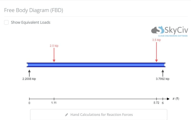
As far as I can tell, this (from a previous post) looks to be about right ...
Screen_Shot_06-07-22_at_04.20_PM_zwirel.png


another day in paradise, or is paradise one day closer ?
 
mikek396, I did not miss it. I made an example. The pulley vector diagram you made is missing the torque.
 
Status
Not open for further replies.

Part and Inventory Search

Sponsor

Back
Top