rapt said:
I was not going to respond again on this topic, but after reading your 4 points above, I think it is necessary
Don't put yourself out on my account. I've got access to most of the Australian Concrete Mafia on this thread. I'm sure that others can chip in if you find yourself otherwise indisposed.
You're likely to find my responses to your responses (below) quite unsatisfying. I apologize for that but really don't know what to do about it. Your statements are just that, statements. You don't seem to feel compelled to back them up with anything resembling proof or physical reasoning.
You've posted over 2000 words in this thread and, to date, not a single sketch. Not one. I suppose you figure that, with you being a PT deity and me being a hapless neophyte, I should just accept your statements as indisputable fact. Unfortunately, if I took that approach, I wouldn't learn a damn thing. And I'm here to learn.
rapt said:
Yes, the calculations will work this way if..[bunch of stuff]
KootK said:
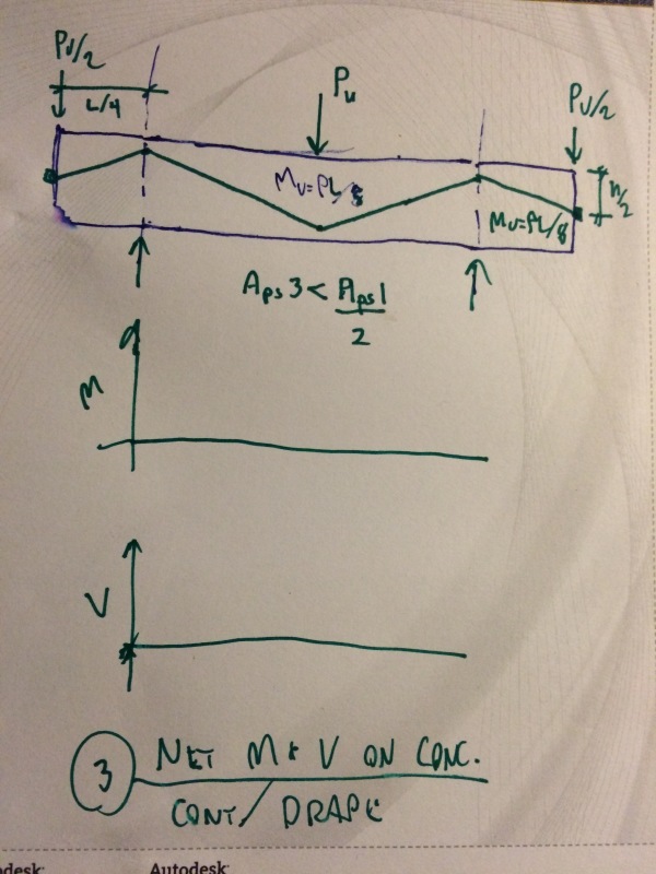
Did I make a bunch of simplifying assumptions? You bet.
If you don't understand why I've taken some simplifications, you are missing the point of the exercise.
rapt said:
- the stress in the tendon at ultimate is the working stress - it is not
We assume that the stress in the tendon is at ultimate level when we calculate ultimate bending capacity the usual way. I fail to see why that same strategy wouldn't work here.
rapt said:
the stress in the tendon is constant along it full length
Again, this is true with the usual formulation and the problem is surmountable. I don't see why it wouldn't work here.
rapt said:
the member is determinate
I disagree. Some additional things would need to be considered in the formulation but, again, that is true of the conventional formulation as well.
rapt said:
the tendons are anchored at the centroid of the section at the ends
I disagree. My derivation assumed indeterminate anchorage placement and seems to work just fine.
rapt said:
the member is prismatic (there are no changes in section along its length)
I disagree. You could take my derivation, change the profile of the bottom of the member any which way, and the result would be the same.
rapt said:
there are no reversal load situations
Load is just load. I fail to see why a change in direction should neuter the method.
rapt said:
the tendon has a single profile shape (no reverse curves etc)
You can calculate balanced load effects at serviceability with complex tendon layouts. I fail to see why it should be any different for the ultimate state.
rapt said:
if you are only interested in an Ultimate capacity and nothing else (ductility, curvature etc) stresses and strains...
KootK said:
I am NOT suggesting that this is a better way to calculate Mu. It's a worse way computationally.
If you think that this is about proposing a
better computational method, you are missing the point of the exercise.
rapt said:
Load Balancing is a calculation tool and that is all it is!
Load balancing is a computational tool and the load balancing effect is a real, physical phenomenon present at all stages during the life of a PT member. What more could you possibly ask of a concept? I fail to see how this is a limitation.
I like to debate structural engineering theory -- a lot. If I challenge you on something, know that I'm doing so because I respect your opinion enough to either change it or adopt it.
")