Fine. The next time that I'm toiling away in a thread and the Australian Concrete Mafia (ACM) shows up, I'll immediately switch my internal label to the
Multicultural Concrete Mafia All Having Significant Ties to the Australian Subcontinent (MCMAHSTAS). The acronym's a bit ungainly but, hey, whatever it takes to maintain political correctness.
Ingenuity said:
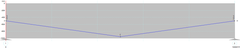
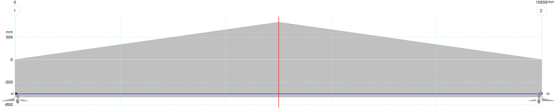
Detail 1 and Detail 2 of your sketches directly above have identical flexural moment DEMANDS at ultimate. The drape does not change the demand. Your M/V diagrams are at SERVICE level loads under the action of EXTERNALLY applied load P, PLUS prestress. These M/V diagrams are not correct at ULTIMATE conditions.
rapt said:
In your last post above, you still have net M and V = 0 for the draped cases! That would imply that the ultimate applied moments have been negated by the prestress.
I believe that you may have misinterpreted my sketches. If you read the titles carefully (my hand writing sucks), my diagrams are
net actions on the
concrete alone. Obviously, I agree that nothing, including tendon drape, changes the actual demand on the member as a whole. However, the presence of the tendons and their drape does effect the ultimate moment and shear applied to the
concrete, examined in isolation. My idea with the sketches was to confirm my understanding that tendon drape effectively moves load from the point of application the columns without really involving the concrete. I suppose that I've implicitly examined a hypothetical case where 100% of the ultimate loads have been balanced. In a real member, the balancing would be less than that but similar principles would still apply.
You guys keep coming back to permutations of AT SERVICE LOADS. I find it strange as I take the following to be self-evident:
1) Draped tendons apply transverse forces to the concrete.
2) #1 is as true in the ultimate condition as it is at serviceability. Perhaps a little more so.
Are we not in agreement on these basics?
rapt said:
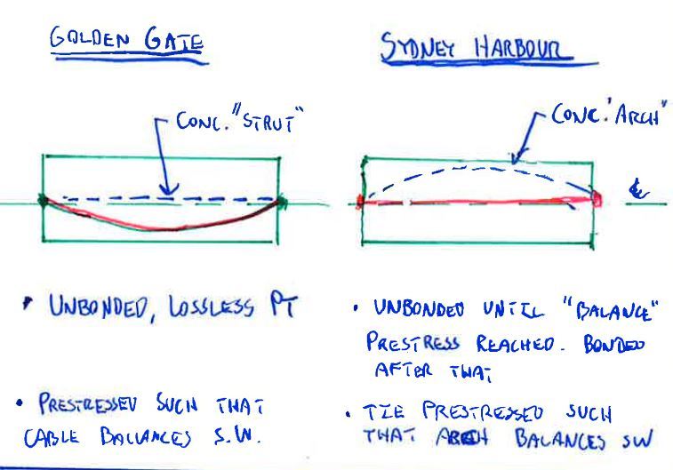
Thinking back to an earlier reply of yours above, you related all of this to the Golden Gate Bridge. That is a suspension structure. A cable structure. A PT member, bonded or unbonded, is not designed as a cable structure, it is designed as a flexural member.
I debunked the golden gate analogy myself above. That's what my sketch on the subject was about. I see the fundamental difference being the fact that, with the bridge, the cables are not anchored to the beam element but, rather to something external. I agree that PT members are not designed as cable structures. But, in many respects, I believe that they
could be.
Early in this thread, I discovered a significant flaw in my thinking. To correct that, I've basically reevaluated PT member behavior from the ground up, starting with statics. As such, I don't want the particulars of "how we design PT concrete" to cloud my developing understanding of "what is the fundamental character of PT concrete". I feel that has been a problem with regard to the focus on the service state versus the ultimate state. It's the same damn balancing load effect at work in
both states. The only difference is our procedural handing of the effect at service versus ultimate.
rapt said:
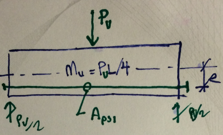
3 is definitely better as a continuous member always is better. But the Area of prestress required will not be less than Aps1 / 2, it will be equal to Aps1 / 2 as the moments will be halved for the arrangement you have defined.
I figured that it would be slightly less than half because the concrete stress block depth would be reduced. It sort of depends on whether or not your looking at it from a balancing load perspective or a conventional ultimate moment capacity perspective though. For 100% balancing, it would be half exactly. For ultimate flexural capacity, a little less than that. I'm still having trouble reconciling the two for indeterminate structures. It's... complicated. Either way, it's a minor point I think.
rapt said:
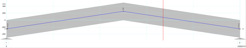
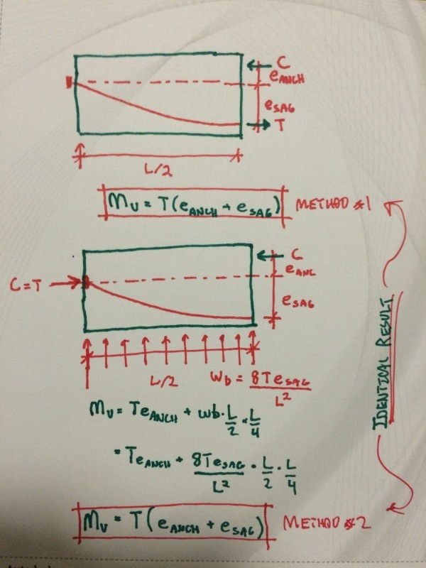
In a Simply supported beam, raising the anchorages at the end above the concrete centroid will not increase the balancing effect as the eccentric anchorages will induce an applied +ve effective moment at each end at the ends exactly equal to the expected increase in balancing effect of the harped profile, completely negating the increase expected (reverse to the effect you have shown for the straight tendon at the ends).
Yup. That was exactly the point of my derivation (detals A&B) on October 25th. Frankly, I've been a bit surprised that nobody's expressed any real interest in that. While I've no doubt that it's out there someplace, I've not yet seen another general proof of the concept. Most people and publications seem to just state it as fact and leave it that. At the risk of tooting my own horn, I thought that my proof was rather clever, particularly given that it requires next to no mathematics.
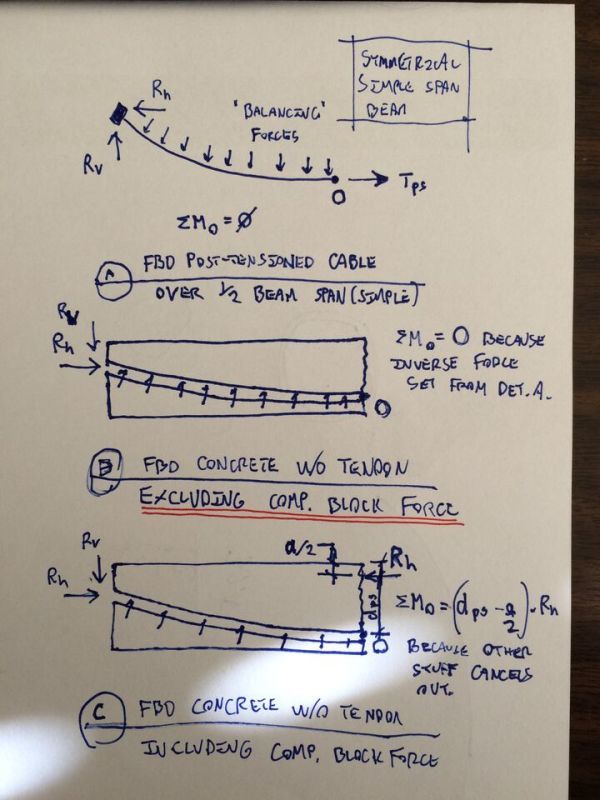
KootK said:
In detail B below, I've examined the equilibrium of the concrete without the PT tendon and, importantly, without the compression block reaction at the section cut. Because the forces that the tendon impose on the concrete are the inverse of those imposed by the concrete on the tendon, I again take the moment summation about point O to be zero. I propose this as non-rigorous proof (to myself) that balancing forces and anchorage reactions form a self-equibrilating system that, taken in concert, do nothing to improve bending capacity.
I like to debate structural engineering theory -- a lot. If I challenge you on something, know that I'm doing so because I respect your opinion enough to either change it or adopt it.
")