Continue to Site

Eng-Tips is the largest engineering community on the Internet

Intelligent Work Forums for Engineering Professionals

  • Congratulations SDETERS on being selected by the Eng-Tips community for having the most helpful posts in the forums last week. Way to Go!

Feature Of Size definition

Status
Not open for further replies.

Sem_D220

Mechanical
Jul 9, 2018
290
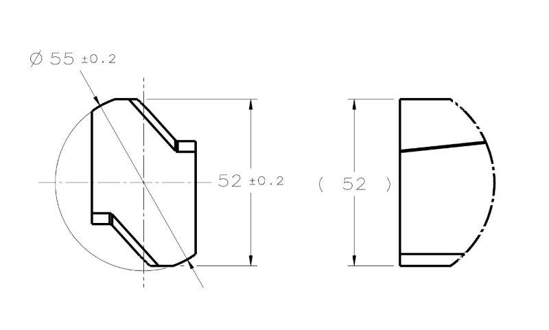
My first question is - according to ASME Y14.5 2009, how would you classify the cylindrical interrupted surface of diameter 55 and the width 52 in the following sketch?
Are they:
- Regular features of size (with interruptions)?
- Irregular features of size type A? (Or maybe even B?)
FOS_QUESTION_aejzhn.jpg


My second question is for those who have access to the 2018 standard:
What is the change that was introduced to the concept of feature of size?
I read that there was a change in the concept in the announcement at the ASME website which pmarc linked to in the thread about the new standard.
 
Replies continue below

Recommended for you

I realize I might be wrong here, but since I am the first commenting on this subject I have to live with that fact.
I would say that Ø55 feature is an irregular FOS because you can drive an UAME from it.
Not sure if anything changed conceptually about FOS in 2018.
 
I think it depends on the geometric control you're planning on using. If it's a profile tolerance to control the 'feature' defined by both the 52 and 55 dimensions then I would think it's an Irregular feature of size, type B. I say this because the angled and planar elements of the feature are not contained within the boundary of a an actual mating envelope that is a sphere, cylinder, or pair of parallel planes.

There's not enough information to say for sure. You'd need to know exactly what the extents of the feature are.

I'm not a vegetarian because I dislike meat... I'm a vegetarian because I HATE PLANTS!!
 
I agree with greenimi - you can obtain a repeatable UAME from the interrupted surface. I am waiting on my copy of 2018 to arrive. ASME says delivery Friday 3/8.

Certified Sr. GD&T Professional
 
Sem,

Your 55 diameter dimension is an interesting case. While it is not a complete 360deg cylinder, it does not look like your typical case of say a 180 deg arc which is comprised of BOTH opposed and unopposed elements - it seems from the way it is shown that it is comprised completely of only opposed elements. I could see an argument in that case that it is a regular FOS - the less controversial claim of course being that its an irregular FOS type A for the reasons mentioned by others.

In regards to the 52 width, I'm not sure that it is a FOS (regular OR irregular) at all since it is conversely completely devoid of opposed elements. Intuitively it seems like we should be able to bound this with two parallel planes, but I don't think it will be able to properly constrain a mating envelope. It could perhaps be type B however I'm not sure about the implications for that. Reading through a related post from some time ago ( seems to suggest it could not be regarded as a FOS - perhaps the thinking has changed since then.

Its interesting to note that there is one similar feature in the standard with figure 2-5 in conjunction with the dimension origin symbol and directly toleranced dimensions, this would seem to suggest that even without opposed elements it is a FOS of some sort however since the dimension origin symbol places additional constraint (ie: full/maximum contact with the indicated side is required) I believe that utilization of the dimension origin symbol is a totally different animal as a result and a similar conclusion cannot be made for standard directly toleranced dimensions.

Edit: Grammar
 
Andrew,

Any chance you could also post the section which defines regular vs. irregular FOS in the 2018 standard (I too am awaiting my copy)? It would be equivalent to 1.3.32 in the 2009 version - this would be most pertinent to the discussion at hand I think.

Side note - I'm interested to see what content was added before the envelope principle which was previously 2.7.1 and is now apparently 5.8.1 - 3 whole sections have been added, unless it was moved. Hopefully this added material has some value and doesn't just up the page count...
 
Thanks everyone for the input!
Andrew, thank you for attaching Rule#1 from the new standard. Would you say it applies to the diameter 55? Diameter 55 would need to be considered Regular FOS for Rule#1 to be applicable. Fig. 5-9 in the attachment shows a regular feature of size with an interruption. I wonder how interrupted a feature can be and still be considered regular. I also join chez311 in the request for a post of the definition of Feature Of Size and its' types.

chez311, thanks for the link. It seems from that discussion that a feature such as width 52 in my sketch may not be considered a feature of size at all. I was planning to control that width for a central location by Position tolerance RFS to a primary datum axis derived from a shank at the extent of the part (not shown in the sketch because of the clipping). There would also be a rotational degree of freedom constrained by a flat that exists on the shank - a secondary datum feature. Do you think it would be a bad practice since the 52 dimension width will fail to "properly constrain a mating envelope"?
 
FOS_-_Copy_g2q6yb.jpg


There is a discussion on linkedin and there are some opinions that E feature it is not an irregular feature of size.

“F" has been agreed that is not an irregular feature of size nor a regular one

“E” not so much agreement achieved.

Copy-paste

“E and F are not irregular features of size either. For these two be irregular features of size the mating envelope - two parallel planes - would need to able to close down on these faces. With these geometry closings parallel planes about the part surfaces would pitch ( or rotate) the part and would not actually close down on these faces.”

“E is an irregular feature of size. This is because we can define a mathematical envelope (2 parallel planes spaced at least 62 apart)”

Correction edit (mistakes in my original post). Hopefully now corrected

"E" from my imbedded picture resembles to yours 52 width feature, don’t they?
 
Sem,

I would say that your 55 diameter feature is less "interrupted" and more "incomplete" as I said it looks to be fully comprised of opposed elements - albeit just not fully 360deg around. This is why I said I could see the case for it being a regular FOS.

SemD220 8 Mar 19 06:28 said:
Do you think it would be a bad practice since the 52 dimension width will fail to "properly constrain a mating envelope"?
Yes I do - I would probably just forgo any possible argument/issues with inspection down the line and specify it as profile if possible.

Kedu,

Your copy-paste of that linkedin discussion highlights exactly what I mentioned in my original post when I said "Intuitively it seems like we should be able to bound this with two parallel planes, but I don't think it will be able to properly constrain a mating envelope" as I can see where both sides are coming from. That said, I lean towards it not being a FOS at all (regular or irregular).
Kedu 8 Mar 19 12:52 said:
“E is an irregular feature of size. This is because we can define a mathematical envelope (2 parallel planes spaced at least 62 apart)”
This is what I meant by "Intuitively it seems like we should be able to bound this with two parallel planes" as I think we can all imagine who two parallel planes could theoretically make up a boundary for this feature.

Kedu 8 Mar 19 12:52 said:
“E and F are not irregular features of size either. For these two be irregular features of size the mating envelope - two parallel planes - would need to able to close down on these faces. With these geometry closings parallel planes about the part surfaces would pitch ( or rotate) the part and would not actually close down on these faces.”
This is what I meant by "I don't think it will be able to properly constrain a mating envelope" since as the boundary closes down the feature will rotate as that boundary closes in, as it is not stable, having no opposed elements. I guess one could specify that the boundary closes in until it makes full/maximum contact with one or both sides (which is essentially what the origin dimension symbol does - perhaps a custom note could accomplish the same if really desired) but thats not really in the definition is it? I guess neither technically is the requirement for being "stable" - however it would be a logical conclusion I think since it is not stable there is no limit to where the contraction will stop, rendering it invalid in my mind. Even features/collections of features having no "directly" (180deg) opposed elements can still be stable as the boundary closes in - see Fig 4-35 in the 2009 version.
 
Andrew,
Thanks for the attachment of the Feature Of Size definition from the new standard. I took notice that there is a definition of the term "Interruption" in the standard. It is a good sign because since it is defined, it is probably further addressed in other places in the standard - something that I felt was missing previously.

chez311 said:
I would probably just forgo any possible argument/issues with inspection down the line and specify it as profile if possible

I envy you :)
Our inspection does not know how to "digest" Profile tolerance. For the 2 flat surfaces 52mm apart, they would not have any issues at all if a horrible thing like 2X 26+-0.1 was specified between the axis and the surface. But they would probably raise questions about a basic 52 and a Profile call out referencing an axis datum and a clocking datum, because they think that Profile is intended mostly to control an accurate form (not location) of features with complex contours and always requires the use of CMMs and programming and what-not. Unfortunately, I don't know enough about metrology to convince anyone otherwise. But these are "my" special case problems, and I agree that ideally, Profile would be a better choice to avoid any "legality" issues.

Kedu, thanks for the reference, these are some interesting quotes from the linkedin discussion. "E" does resemble the feature from my case dimensioned by 52+-0.2.

chez311, Kedu, I have my doubts about this statement from the linkedin discussion:

"E and F are not irregular features of size either. For these two be irregular features of size the mating envelope - two parallel planes - would need to able to close down on these faces. With these geometry closings parallel planes about the part surfaces would pitch ( or rotate) the part and would not actually close down on these faces"

"F" is obviously not a Feature Of Size. As for "E", I'm less convinced by the quoted argument.
For this type of geometry, the mating envelope would have to be simulated as part of an inspection of Position control (or a center plane orientation control, for that matter). When simulated by physical gauging equipment, the part will have to be immobilized in a fixture with its' degrees of freedom constrained according to the referenced DRF. The specified DRF can prevent the rotation of the part during the simulation of the actual mating envelope, and there might not be an issue at all. Am I missing something?
 
Sem,

I should not have said there would be no issues. What I mean that I figured for a "by the book" legality standpoint it would be better and also more digestible by an inspection department. Perhaps thats not the case, but would they then have then no issue with you applying a size tolerance to the referenced feature?

To your second point, I agree that a RAME will be determinable for a position/orientation tolerance as long as it is sufficiently constrained to the DRF to prevent the unwanted movement. That said, a UAME will not be determinable and the concept of "size" will have no meaning.
 
chez311,
If by "applying a size tolerance to the referenced feature", you mean 52+-0.2 (although this feature is not "referenced" as in datum references, so please clarify if you meant something else), they would probably not mind the size specification, as long as they manage to measure it. But I do understand that it is problematic; since according to what I've learned today it is probably not a feature of size, it should probably not be directly toleranced as well.

Speaking of that issue, I wonder if the new standard still shows direct +- toleranced dimensions on non-FOS like in fig. 2-4 in the 2009 version.

I understand your point about the difficulty to simulate the UAME for non-opposed "width" features.
 
chez311, I just realized something that made me question our conclusion about undeterminable UAME for "E" type features:

chez311 said:
To your second point, I agree that a RAME will be determinable for a position/orientation tolerance

Actually, when you look for the axis or the center plane of a feature controlled by Position/Perpendicularity/Parallelism/Angularity RFS, you are looking for the UAME, not for the RAME. Think of it this way - checking the orientation of the center plane of the RAME is redundant, as the RAME is basically oriented to the referenced DRF. So, since the part is immobilized according to the DRF during the UAME simulation, I suppose that the unwanted movement is prevented after all. The thing to realize is that the part is constrained, but the simulated UAME is not constrained to the DRF, it merely follows the as-produced the feature. However, it can be simulated in a repeatable way. What do you think?

 
Sem_D220,

Datum reference frames are not involved in the determination of unrelated actual mating envelopes.


pylfrm
 
pylfrm -- read his post again. It's true that a DRF doesn't determine the UAME, but the UAME has to be derived for many geometric controls in order to compare that UAME to the DRF (such as positon or perp that he mentioned).
 
Belanger,

To be more specific, I disagree with this statement:

So, since the part is immobilized according to the DRF during the UAME simulation, I suppose that the unwanted movement is prevented after all.


pylfrm
 
Thank you, Belanger.

What I'm saying is that if a position control, for example, was applied to 52 size feature in my sketch referencing datums that constrain all rotational degrees of freedom for the part and 2 translational degrees of freedom perpendicular to a datum axis (which is designed nominally parallel to the center plane of the 52 size feature), the inspector would not experience any problems during simulation of the UAME of that feature. Again, the UAME is never constrained to any datums, but the part during UAME simulation is (in this case).
 
Sem D220 said:
the inspector would not experience any problems during simulation of the UAME of that feature. Again, the UAME is never constrained to any datums, but the part during UAME simulation is (in this case).

I'm not sure it matters how the part is physically held during simulation/measurement of the UAME - it doesn't change the fact that as pylfrm noted datum references are not involved in the creation of the UAME - by definition it is not constrained to any datums, only to the feature itself. Even if the part can be fully constrained this would only aid in the determination of the RAME, but would not prevent or limit the pitching/rotating of the UAME as it contracts around the feature.

I stand by what I said before that I do not believe a UAME is determinable for a feature of this type. If you disagree, could you maybe provide an example of what you think it would look like? Furthermore the concept of size I do not believe has any meaning either as it lacks any *opposed points (which in turn is also the reason a UAME cannot be created). Y14.5-2018 provides some clarity here which perhaps helps in some previously indeterminable cases (for example - if instead of 2x we had 3x offset planar features lacking *opposed points) but not in this one as it still requires the establishment of a UAME. As a side note, I am curious as to how this jives with either math standard (1994 or 2018) - my guess is it doesn't since per the discussion here ( it was commented that the new Y14.5.1-2018 is only fully compliant with Y14.5-2009...

*Edit: re-reading this I realize I lack the proper terminology here. Even replacing opposed with directly vs. indirectly opposed points seems equally ambiguous. Hopefully it can be easily visualized how 2 offset planar features of the type shown in the OP would be "unstable" as a boundary contracts around it, while adding a third offset feature would "stabilize" it. If that or my original meaning is not clear and a figure/example is needed someone please let me know.
 
Status
Not open for further replies.

Part and Inventory Search

Sponsor