Continue to Site

Eng-Tips is the largest engineering community on the Internet

Intelligent Work Forums for Engineering Professionals

  • Congratulations waross on being selected by the Eng-Tips community for having the most helpful posts in the forums last week. Way to Go!

Fire torch warning... Pressure created by resistance to flow?? 11

Status
Not open for further replies.

akkamaan

Agricultural
Jun 20, 2010
109
For a hydraulic guy to say that pressure is created by resistance to flow is like an electrician would say that the resistor creates the voltage...Right!?[ponder][bigglasses]

Listen to
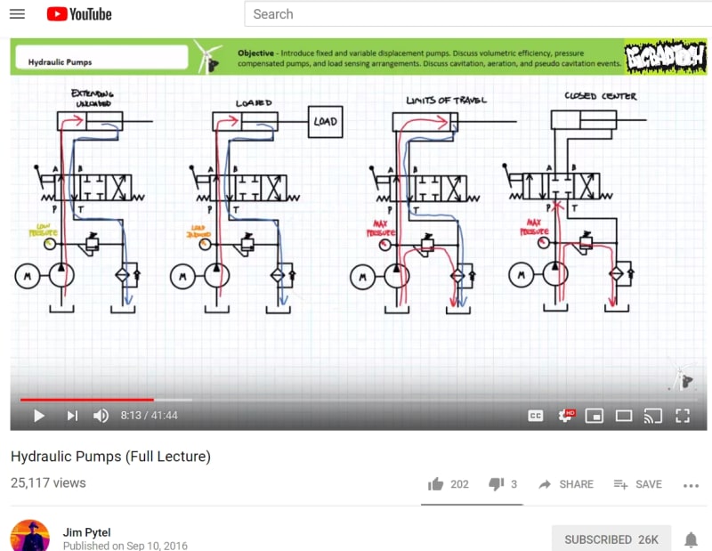
Jim Pytel, Columbia Gorge Community College
in his Youtube lesson

jim_pytel_twrcgf.jpg


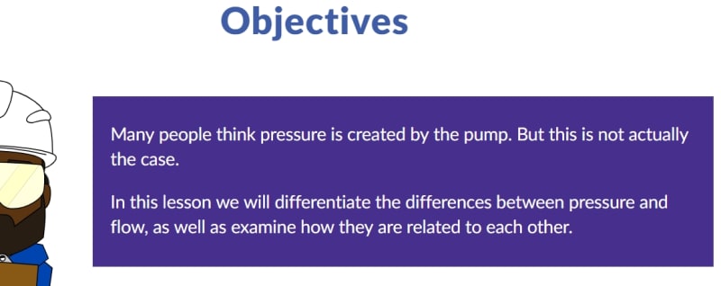
LunchBoxSession

lunchbox2_cmml6w.jpg


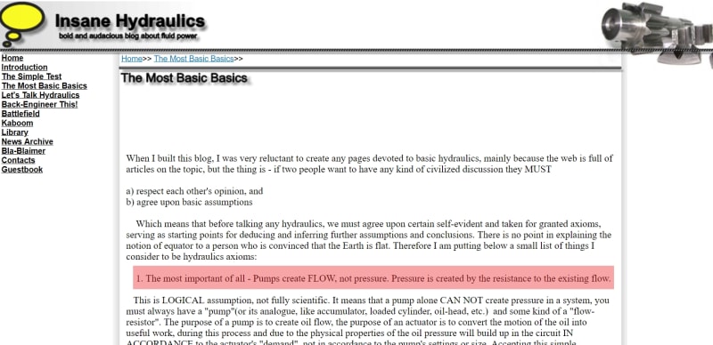
Insane Hydraulics

insane_hydraulic_statement_v2ynwk.jpg
 
Replies continue below

Recommended for you

IRStuff said:
No resistor on Earth will generate a voltage without a voltage field, ever.

Try this:
No woman on Earth will generate a baby without a man, ever.

Nobody was arguing that.

So this brings us to the crux of the discussion. There is no such thing as a voltage field without a resistance to current flow, though I’ll listen if someone wants to explain how you could have both voltage and no resistance to current flow.

The implication in the original post refers to the resistor in a circuit.

So, I presume that you would not disagree that the resistor creates the voltage in a circuit, recognizing that a voltage field is solely created and solely exists by the prevention of (resistance to) current flow.

Therefore, I will not entertain the notion that a battery creates a voltage or that a pump create a pressure or that an accumulator creates it, either, and that neither voltage nor pressure exists until something is introduced (resistor, air gap, switch, valve, plug) to prevent or resist the flow.

Pressure is created by resistance to flow as voltage is created by the resistor in a circuit . You do not get pressure or voltage, either one, unless and until you are preventing or restricting flow.

Engineering is not the science behind building. It is the science behind not building.
 
akkamaan said:
If we have a "12V" battery resting and no circuits that draw currency there is no voltage differential?

Sure there is — solely because between the positive terminal and the negative terminal there is an enormous resistance to flow - a nearly infinite resistor commonly referred to as “air.” You do understand that an infinite or nearly infinite resistor is still a resistor, right? That resistor is what is allowing for a voltage to exist between the battery terminals.

You can replace that resistor with any of a great number of other resistors and your voltage will drop accordingly. Lower the resistance to flow and you get lower voltage measured on your battery. Put a small LED lamp on it and you’ll see nearly 12 volts across your terminals, due to the extremely high resistance. Put a lower resistance resistor, such as a lawnmower blade, across the terminals and then see what your voltmeter reads. Since you are lowering the resistance, you get a lower voltage. Try it sometime.

akkamaan said:
Or a source of hydraulic pressure but no flow, an accumulator, a cylinder at rest on confined pressurized fluid, or a constant pressure pump, there is no pressure differential?

Um... yes — there is a pressure differential between the contained fluid and the place that you’re standing, presumably outside of the accumulator or hydraulic circuit. This is because the flow of the fluid is resisted by the shell of the accumulator and the body of the hydraulic cylinder and the pipes, hoses, etc. The pressure is created by resisting the natural tendency of the contained fluid to find its way to an area of lower pressure; the differential area is created by the boundary of the containment system. If you crack a valve, the pressure as measured at the outlet port of the accumulator or pump will be reduced. Open it up wide and it will be significantly reduced, because you have reduced the resistance to flow.

akkamaan said:
And what is inducing the pressure in the pressurized hydraulic system with 0 GPM flow? Is it the "bottom of the pressurized cylinder at rest" or the force from the mass (source of energy, prime mover) resting on the cylinder piston?

It is all of that plus the closed hydraulic system itself containing the fluid, resisting it from flowing anywhere, i.e., back to the tank or onto the shop floor.

I can't understand how people high up in the recognized fluid power hierocracy (see the 3 examples in my opening post) can say that pressure comes from the resistance to flow.

Hmmmm.

Engineering is not the science behind building. It is the science behind not building.
 
Your argument fails because there is always an active force, pressure or voltage behind any motion. And there is no active energy component in a dead resistor or load. You can't increase the voltage or pressure by increasing the resistance. Pressure or voltage has to be increased on the prime mover side of the equation.

Usually, your arguments come in combination with the "flow makes it go theory". There is no energy in "flow", Flow is just a way to describe the velocity of gases an fluids. Only torque (Nm), force (N), pressure(N/m[sup]2[/sup] has the necessary "Newton"-component. That's why pressure/voltage can come from the resistance.
But resistance is a conditional factor for how high pressure or voltage we need to express from the source of energy to be able to move the load or overcome the resistance.
 
Your argument fails because there is always an active force, pressure or voltage behind any motion.

Let's see how that works. Try this real-world experiment. Put your hand straight out, facing up and place a postage stamp on your palm. Now apply 10 pounds of force straight upwards to the postage stamp. Can you do it? Why not? You can raise your hand as fast and as hard as you like, but you are still never going to apply 10 pounds to a postage stamp in free air. Why can you not do it?

Now take a 9.9 pound package of printer paper. Place it in your outstretched palm and apply 10 pounds of force upwards. Hmmm... where you could not create any appreciable force on the postage stamp, now suddenly, you can apply a force to this. In other words, your attempts at applying a force failed until you have a resistance. Note that this will work whether you try to do it up, down or sideways.

Your statement that an active force, pressure or voltage being behind a motion does nothing to refute the statement that pressure is created by resistance to flow.

You can't increase the voltage or pressure by increasing the resistance.

Yes. Yes, you can and that is exactly what happens when you close a valve or turn up the knob on a potentiometer. I have explained that twice in what happens with your car battery.

Pressure or voltage has to be increased on the prime mover side of the equation.

That is wrong because it is not possible to do anything with your battery, generator or pump to increase pressure.

The electrical analogy:

Yank the rope on your generator and where does the voltage come from? Where is the voltage once it starts reading 120V? If you tied the two terminals together, where would the voltage go?

If you replaced the windings with solid copper plate, what would happen to the plate as the magnetic field passed by it 60x/second? What is eddy current heating? If you took the copper plate and cut a big hole in the middle and then saw cut one side so that you have an incomplete hoop, what would you see between the two faces of the saw cut? Would it be some measurable voltage? If you pushed the two faces together, where would the voltage go? Could you measure any voltage anywhere on the entire loop with the two faces pushed together? If you introduced a resistance to current flow by opening up the saw-cut gap again, would you measure a voltage between the two faces? If there is no voltage when the air gap is gone and you get a voltage reading when you re-introduce the air gap, then what creates the voltage? How is that similar or dissimilar to a single turn of bare wire? How is that similar or dissimilar to a single turn of insulated wire? In what way is that similar or dissimilar to a hydraulic pump?

The point is that neither a generator, nor a power plant, nor a battery "create voltage".

The mechanical analogy:

Take a gear pump and disassemble it. Surprisingly, or perhaps not, the driving pinion is often an involute spur gear profile that will mate quite nicely on a rack. Now mate this exact gear pump pinion to a rack and turn the pinion. Voila! The rack moves back and forth, just as it will on the steering in your car. Now, allow unrestricted movement of the rack and tell me what kind of stresses (coincidentally, measured in psi) are created in the cross-section of the rack. Save for the inertia of the rack itself, you get pretty much zero stress (psi) in a cross-section of the rack when there is no resistance to movement of the rack.

Now, attach the far end of the rack to a plow or shovel or some form of resistance and observe the stresses in the rack. More resistance from the load and you get higher stresses in the cross-section of the rack. Now attach the end of the rack to something that will not move. Attempt to turn the pinion. Extreme stresses (psi) in the rack and yet... no movement. That is to say, there is no flow of teeth passing a fixed observer. Apply a load cell into the system while the far end is fixed. Try to turn the gear back and forth. What does the load cell read? Is that similar to a pressure gauge in a hydraulic system? Does the load cell show fluctuations in force as you attempt to turn the pinion back and forth? If you know the cross-sectional area of the rack, can you use the information from the load cell to determine the stress in the working medium of the power transmission element (i.e., the rack in this case or the fluid in a hydraulic system)?

Now, imagine that you place a clamp on the rack that is attached to the source of resistance to movement of the rack, such that extreme forces in the rack will cause the clamp to slide along the joint. What will be observed when the final load is fixed and the pinion/rack is forced to move? Will there be significant heating caused by the clamp dragging? Will the work/energy of the rack moving back and forth be dumped into friction between the clamp and the rack? Can it be noted that on the downstream side of the clamp, there will be no movement of the load? Could you call something like that clamp a stress relieving mechanism? Is that similar to a pressure relieving valve in a hydraulic system?

Now, put the pinion back into a housing and fill it with a fluid. The exact same pinion is now moving fluid instead of a rack. Whether it is moving a rack or a volume of oil, the movement of the medium (rack or oil) must take place for the shovel or plow or whatever implement to move or "go." In other words, the flow of either fluid or solid must occur for something to go, or more succinctly, the flow makes it go.

Finally:

I have seen the idea posted multiple times on this board that somehow "flow makes it go" is wrong. Each time I have seen it, there has been a significant amount of detail that has a "then a miracle occurs" step between the theory and the conclusion that somehow flow doesn't make it go. So here we are. I have put my cards on the table and will eat crow if someone will correct my thinking and analogies, but the correction has to be correct both theoretically and in the real world. I'm sure that it's been explained elsewhere, so I'll read an article or three that is on a non-ET website if it will explain just how "flow makes it go" is wrong. So let's see it.


Engineering is not the science behind building. It is the science behind not building.
 
I suppose the is a corollary, if it does not go there is no flow.

Ted
 
I see the hydraulic system as an energy transfer device or mechanism or system. Both pressure and flow or force and velocity must be present. Otherwise you have only the capacity to do anything.

Ted
 
Pressure and flow are interrelated. So it can be somewhat confusing as to which causes what. As hydtools points out, though, the flow of energy through the process is pretty straightforward. Remember one of the most fundamental principles of science, energy cannot be created or destroyed, only converted from one form to another.
 
Do the pneumatic people also say that 'flow makes it go' ?

If so I'd better make sure my bike is chained down the next time I pump up its tyres (sorry, tires).
 
Solving any engineering problem involves simplifying assumptions. "Flow makes it go" is not an expression that I would use, but inherent in it is the assumption that liquids are incompressible and and that expansion of hoses are not an issue. These assumptions are very common in many engineering problems, but not always accurate.
 
Can anybody think of cases where there is pressure without flow being involved? If I put a book on the table the pressure on the table is mass*g/area. Does the table create the pressure or the book?

Do the pneumatic people also say that 'flow makes it go' ?
I have never heard that from someone doing pneumatic controls but then I haven't seen many people do real pneumatic controls. Obviously it is not true. Both air and oil are compressible it is just a matter of magnitude. So why do hydraulic people say flow makes it go?

Solving any engineering problem involves simplifying assumptions. "Flow makes it go" is not an expression that I would use, but inherent in it is the assumption that liquids are incompressible and and that expansion of hoses are not an issue. These assumptions are very common in many engineering problems. but not always accurate.
Our tech support guys hate hydraulic designers that make the assumption stated.
Oil is definitely compressible. It is more compressible if there is entrained air. Hydraulic designers often do not know the formula for natural frequency. The bulk modulus of oil, compressibility, is part of that formula. The natural frequency limits how fast a hydraulic cylinder can accelerated or decelerate. I wrote an H&P article about this. Hoses expand a lot. They are the main culprit in lowering the natural frequency. What makes matters even worse is that the hose, or solid piping, add to the compressed volume of oil and even worse is the fact that the speed of sound or pressure waves are not infinitely fast in oil. It is roughly about 4ft/millisecond. The length of hose on this project
was 40 ft which created a 10 millisecond dead time. There is no point in having fast motion controller if the hydraulic 'designer' is going to handicap the controller with hose.
One of our engineers was operating the hydraulic controls. The normal TV guys may have had PhDs but they knew nothing about hydraulic controls. Most so called 'hydraulic designers' no little about designing a hydraulic servo system.

Peter Nachtwey
Delta Computer Systems
 
Peter, you are completely correct, but most hydraulic power systems are are not servo-systems. Hydraulic systems have been around for hundreds of years, long before electricity was commercialized. It was electronic controls that allowed servo-systems to be developed, first with electric motors and that slowly trickled into hydraulics. You do not need Laplace transforms to design a wood splitter. Just keep that in mind. You need to know your audience.
 
Peter, you are completely correct, but most hydraulic power systems are are not servo-systems.
Ask yourself "where is the money?". Do you want to be in the wood splitter business or the high tech business?
Why don't we weight what is important by how profitable the business is? Think value added.
Back in the mid 1990s I was sitting in front of the VP of a major hydraulic company. He dismiss us by saying that hydraulic servo control is only about 5% of the market and high risk. At the time my thoughts were "there is an opportunity to grow"


Peter Nachtwey
Delta Computer Systems
 
I retired from what I thought was a very satisfying career. The design, development, and production of pneumatic and hydraulic powered tools for the mining and construction markets. Servo controls were not involved. There is a bigger world in which to work.

Ted
 
EngineerTex said:
Let's see how that works. Try this real-world experiment. Put your hand straight out, facing up and place a postage stamp on your palm. Now apply 10 pounds of force straight upwards to the postage stamp. Can you do it? Why not? You can raise your hand as fast and as hard as you like, but you are still never going to apply 10 pounds to a postage stamp in free air. Why can you not do it?
Why would I want to push "a stamp out to the stratosphere in one second"?
Pressure is not the purpose with hydraulics, it is the motion of an object we want to accomplish. If I want to move that stamp 1 foot upwards in 1 second with my arm I do it by lifting my 10000 times heavier arm. Not a lot of extra force needed
Let's say that stamp has a mass of 0.0001kg I apply 50N (approx 10 lbs)it will accelerate with Newtons Second law of motion, F=m×a, or a=F/m, a=50/0.0001=500000m/s[sup]2[/sup].
But where is the engineer that tries to design an application that induces a certain pressure or force rather than a certain motion with a specific velocity? Whatever application there is, work has to be done. Work takes energy. Work is the product of force and distance. Even if it is a "static" press, there has to be some compression or motion (work/energy/pressure×volume) to accomplish the applied force. And the object in the press is not moving so the compressing (force/pressure) motion has to come from the prime mover.
 
Why would I want to push "a stamp out to the stratosphere in one second"?

Who knows? Even if desirable, such a thing is impossible with the prime mover (your hand.) It illustrates that even if your arm is capable of applying a force of 10 pounds, it cannot do so without something to resist that 10 pounds, similar to how a pump that can push fluid against all sorts of pressures, can't do anything besides spill fluid all over the floor if there is nothing to resist it.

akkamaan said:
Pressure is not the purpose with hydraulics, it is the motion of an object we want to accomplish.

akkamaan said:
And the object in the press is not moving

Um. Ok.

Anyway. For everyone else reading this, the fluid doesn't really care about what we want to accomplish. The object in the press is moving. It is being compressed. And the press itself and the object in the press together resist the movement of the fluid in all three dimension. This is where the pressure comes from. The pump provides fluid flow. The resistance to that flow is what creates the pressure, whether the calculations describing the system include high frequency effects like fluid inertia and elasticity of a hose, or low frequencies, like the movement of a cylinder rod.

Resistance to twisting is what causes torque in a driveshaft.
Resistance to movement of the crane hook is what causes tension in a cable.
Resistance to movement of the bucket is what causes bending in a backhoe boom.
Resistance to fluid flow is what causes pressure in a hydraulic system.

Engineering is not the science behind building. It is the science behind not building.
 
Tex your statements are useless for any type of problem solving. So pipes create pressure. That's useful knowledge.
 
If resistance to flow does not result in pressure, why are we concerned with pressure at the outlet of actuators in motion? That pressure we call backpressure. There is only resistance to flow in a return line as fluid flows from the actuator to the reservoir which is usually vented to atmosphere.
In the force balance equation for extending a cylinder there is a force term resisting piston motion and is described as that force necessary to push fluid out. Force to push fluid seems to imply a resistance to flow.

Ted
 
Compositepro said:
Tex your statements are useless for any type of problem solving.

Respectfully, I disagree.

Identical engines are used in a wide variety of vehicles. Knowing that vehicle weight, tire size, rated approach angle, etc. are what dictate drive shaft size is an important thing to know.
Knowing that the load on the end of the cable is what controls the cable tension is an important thing to know if you need to keep a crane mast from being torn down.

The point of bringing up all of these analogies is that just as in hydraulic systems, in order to determine certain aspects of the system, one must look at the load, rather than the energy source.

Most importantly here, the audience of the videos originally referenced is filled with introductory-level fluid power designers, mechanics and technicians. Understanding why a pump being turned at a constant speed will show widely changing pressures, due solely to a changing load, is a very important thing to know. Resistance to flow creates the pressure in a hydraulic system in the same way that resistance to current flow is what creates the voltage in an electrical system and if a person does not have his mind wrapped around that concept, he will have zero understanding of the why and how a fluid power system works. This concept is equally important to know for advanced fluid power system designers.

Engineering is not the science behind building. It is the science behind not building.
 
EngineerTex, you are missing the point. Resistance to flow does not create energy. This is similar to IRStuff's comment about resistors do not create voltage. You also seem to forget that it takes pressure/force to accelerate a mass of oil out into a void.
Pressure is just a form of energy a fluid might have. There is heat, pressure, kinetic, potential etc.
So how does one use an equation to calculate pressure?
Look at this very long and pretty detailed simulation of a hydraulic cylinder.
Where do you find an equation that indicates pressure is resistance to flow?
Your argument is similar to the "flow makes it go" guys that say V=Q/A but they assume the know what the flow is when in truth the flow happens because of motion, flow doesn't create it.
The closest equation I can think of is Q=K*sqrt(ΔP)or (Q/K)^2=ΔP but that is just a change in pressure, not the absolute pressure.
Look at the simulation, basically it is integrating changes in pressure with respect to time. The pressure changes add or subtract from the absolute value.
In short, P = P0 + (Q/K)^2
The best you can state is that pressure is the resistance to flow plus the pressure of some other pressure state. P0 could be a 0 or it could be 1 atmosphere.

Technically HydTool's post above should be I = ΔV/R


Peter Nachtwey
Delta Computer Systems
 
Status
Not open for further replies.

Part and Inventory Search

Sponsor