Eng-Tips is the largest engineering community on the Internet

Intelligent Work Forums for Engineering Professionals

fixed and pinned supports

Status
Not open for further replies.

abdallah hamdan

Structural
Oct 13, 2021
32
0
0
PS
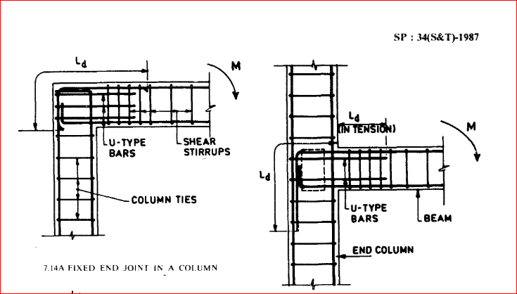
if I have a beam with pin supports (columns) as in fig (1)
1_s8in4c.png


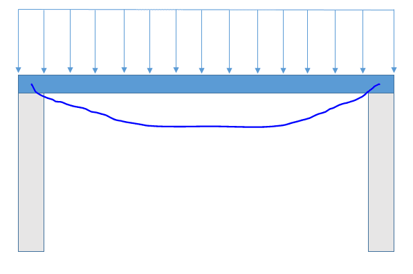
Is having a weight P due to the existence of upper floors on the beam sides as in fig 2, lead the beam to act as there is fixed support on both ends?
2_mgssog.png
 
Replies continue below

Recommended for you

it would depend IMHO on the geometry of the beam and the attachment of the beam to the column.

if a uniform beam, then fixed ends are unconservative. If a variable section, then maybe assume fixed ends to size the ends and simply supported to size the mid-span.

if the end fastener pattern is capable of handling moment then foxed ends are reasonable, if not, then not.

another day in paradise, or is paradise one day closer ?
 
abdallah hamdan said:
...must the beam end always be designed as pinned supports be more conservative?

That will give the highest positive moment in the span, so it's conservative for that.

There could be some negative moment at the supports. If this is a concrete beam, then you'll need some reinforcing steel at the top to handle it. For example, in the ACI 318 Table 6.5.2, there are simplified expressions for bending moments. For the case of "Interior face of exterior support" and "member built integrally with supporting column," the negative moment would be Mu = wu Ln^2 / 16. Short of a detailed analysis, I would design the negative steel for at least this much.
 
so, what should I do, assign a fix or pin support at end of the beam?
or should I assign a partial fixity for beam ends that will give a reaction moment of "wu Ln^2 / 16" at beam ends
 
abdallah hamdan,

You are misusing the terms "pinned" and "fixed" supports. A pinned support permits free rotation but does not permit translation. A fixed support permits neither rotation nor translation.

The beam in your first diagram is best analyzed using a pin and roller support, if the beam is hinged to the column.

The beam in your second diagram is best analyzed using a rotational restraint at each end commensurate with the stiffness of the beam and columns. The load 'P' at each end contributes negligible rotational resistance, but if the beams and columns are rigidly connected together, the moment may be substantial.

The answer to your question depends on the stiffness of the members coming together at each joint. An analysis can be carried out to determine end moments on the beam. In some cases, you may wish to estimate the end moments based on experience or values permitted by code.

BA
 
If it's constructed, assuming a slab clamped in a stairshaft wall or elevator wall, I generally treat them as fixed end. If cast into a keyway in the wall then I treat it as pinned. If in a keyway, but at the corner of a wall, I treat the top reinforcing (only the top) as being fixed at that corner with whatever contributing moment I calculate.

Rather than think climate change and the corona virus as science, think of it as the wrath of God. Feel any better?

-Dik
 
BARetired has it right. In reality, building structures rarely have either purely fixed or purely pinned connections. I use 'rigid' for a connection which has a substantial amount of bending moment, and account for that rigidity in design, if not in analysis.
 
If I have 20 storeys of a concrete shaft coming down with a 6" or 8" slab 'pinched' between the walls, I would normally consider that as being pretty nearly a fixed conditon.

Rather than think climate change and the corona virus as science, think of it as the wrath of God. Feel any better?

-Dik
 
dik thats a part of my question, how many stories above are to consider it fixed, or is there any way to ensure the fixity of the support? by detailing maybe
I have been searching for 3 days and found that extending negative moment bars in a column by development length will develop fix joint between column and beam, but I don't know how many bars must be developed and have no clear vision about this detail
if not by detailing, can I calculate the (sum stiffness of column/sum stiffness of beam) ratio at the joint "a" (Ψa) and if it's very small I will consider it fixed support? isn't that a strong beam weak column situation?
ds_ajhwxu.png
 
I disagree with dik, and would always consider the connection of a floor slab to a core wall to be pinned...for the slab design. Some engineers would be less conservative, but the method of construction is likely to intervene. For example...if the core walls are slip formed as a result of a decision by the builder.
 

Happens, I guess... in these environs, core walls are not generally slip formed and the slab is clamped between stories.

Rather than think climate change and the corona virus as science, think of it as the wrath of God. Feel any better?

-Dik
 
I have reached to point and I think it's true
these are details for fixed support based on "SP 34", and these are similar to the moment-resisting frame joint details
122_ipxant.png
121_bsphlw.png

so if I want to assign fixed support between column and beam I will provide this details in the design, thanks all
 
I think some clarification is needed. The OP is referring to Fig. 7.14A of SP34, "Handbook on Concrete Reinforcing and Detailing" in which the term "FIXED" is used.

A beam may be fixed to a column, meaning that the beam and column are rigidly connected, hence have equal rotation. That does not mean the beam has a fixed support, because, as hokie66 pointed out, the joint will rotate when load is applied to the beam. The amount of rotation depends on the stiffness of all members meeting at the joint.

Capture01_fdjrqq.png


Capture_dkzmmc.png


BA
 
Status
Not open for further replies.
Back
Top