Continue to Site

Eng-Tips is the largest engineering community on the Internet

Intelligent Work Forums for Engineering Professionals

  • Congratulations KootK on being selected by the Eng-Tips community for having the most helpful posts in the forums last week. Way to Go!

Flow stall after pipe drops down 9

Status
Not open for further replies.

markboc

Bioengineer
Sep 1, 2020
19
Hello,

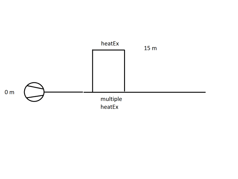
we have the following problem: A heat exchanger (15 m) is fed by a pump (0 m). It is a pipe network where other heat exchangers on parallel pipes are located much lower. The pressure gauges read low to negative pressures right before and behind the heat exchanger. Throttling behind the heat exchanger seems to solve the problem. It is suspected that the flow stalls after the heighest point of that branch of the piping system. Nonetheless the flow rate through that branch is higher than through the branch that contains the other heat exchangers, located lower.
image_w5kpc4.png


1) Can anyone direct me to literature or suitable key words for google, to get more information on the problem of the flow stalling? We suspected because the flow experiences a free fall and accelerates the vacuum in the heat exchanger is created.

2) Another mitigation which was thought of: install a throttling valve behind the pump before the pipes branches in order to increase the pressure. The increased pressure should make sure that the 15 m heat exchanger is supplied with medium. My questions here are:
2.a) The pump head matches the pressure losses of the pipe network. If I install a throttling valve the pressure will rise, but only before the valve. The increase in pressure should match the pressure drop across the valve. So in my opinion it is not possible to control the pressure in the pipe network with this method.
2.b) I am correct in assessing that the pressure at branching point does need to be greather than 15 m + pressure losses across the pipe + pressure loss across the heat exchanger. I suspect this does not pose a problem as long as the pressure loss across the other path is high enough. This would lead me to think we can ensure proper operation by throttling in the branch where the 15 m heat exchanger is NOT located.

Basically I'm trying to determine at which points we can try to control the flow in a manner, where we have no negative presssure at 15 m.

I'd appreciate your input on the situation,

have a nice weekend!
 
Replies continue below

Recommended for you

This is an simple problem and a solution can be found if you would supply a complete flow diagram. Add the flows, pipe diameters, and valves onto your sketch. Is this a recirculating loop?
 
A picture is worth 1000 words. Maybe 1,000,000 words if you talk about pipe networks!

Please make an accurate network diagram. Show all equipment in proper place, known flowrates and pressures at the points in the diagram. Show all pipe lengths, diameters and elevations.

15m could be length or head. Please make that clear, or show pressures in bars or psig.

You usually don't want to throttle the pump unless there is too much pressure or flow.
Valves in front of the heaters ... maybe.

Give us a nice diagram, then we can talk intelligently. Otherwise .. there is no otherwise.
Ball is in your court.

 
markboc,

No one can really figure this out as your description is confusing.

What exactly is yur problem? No flow through the highest HX? Is that waht you mean by the flow "stalling?"

PLease use descriptions such as up stream or downstream. "Behind" is too vague.

Assuming you mean that the valve is downstream of the junction point from the other HX's, you might be getting more flow if the pressure losses for the same flow rate are lower for the higher HX than the lower ones, i.e. it is short circuiting the flow.

In any closed system you normally pressurise the loop such that the highest point is above atmospheric pressure. Then all you need to do with your pump once you've removed all the air is overcome frictional losses.

Your questions
1) Try closed circualtion loop
2) Makes no sense to put the valve U/S the junction point. You are correct - won't work
2b) Yes you are correct.

As said by others - Is this a closed system or open?. If a closed system then you normally need a pressurisation input to keep the pressure constant. If an "open" system then you might need pressure control D/S the high heater to stop it pulling a vacuum in the HX or causing the water to boil at sub atmospheric pressure.

But see 15-03s post and see if you can give us the required information. It's not a hard system.

Remember - More details = better answers
Also: If you get a response it's polite to respond to it.
 
You say "we have the following problem". What problem? I did not see one. Negative pressures? Why is that a problem? Flow stalling? What is that?

It sounds like you may be suffering from vapor lock where air is accumulating in the higher heat exchanger, but who knows?
 
Please give this person time to provide appropriate information.


Thank you all for your input! I also realized prior to looking back at this thread that my post may have been confusing and I wasn't wrong. Let's start again.

image_ytetqf.png


This is a recirculating loop, the tank is vented if the symbol I drew there isn't clear.

This is the current situation and I supplied all information I have. Pipe diameter is DN500, exception: the two branches containing hx1, hx2, hx3 are DN200. The overall length is a couple of hundred metres. I don't have an isometry at hand. The medium is water.

1) The pressure indicators PI 1 and PI 2 indicate negative pressures and hx1 is often damaged. We suspect due to the vacuum occuring there. The idea here is that due to the free fall D/S of hx1, the fluid accelerates and the flow stalls. I'm an ESL speaker, so I don't really know how to describe this better. If 500 m^3 / h go in and the fluid velocity increases, then more than 500 m^3 / h would need to flow D/S of hx1, unless the wetted crosssection in the pipe decreases. This should reflect my original question 1), I'd like some further information on this phenomenon or at least a better description so I can find out myself.

2) Throttling V1 seems to solve the problem or so have I been told. If the acceleration / stalling theory from 1) is correct I can understand this.

3) The current idea is to use V2 to control the pressure U/S of hx1. This is where I have the most trouble in understanding / I'm opposed to the idea. I think every increase in pressure due to throttling V2, let's say the 6 bar rise to 8 bar, wouldn't change the fact that we still had 3.5 bar U/S of the junction point. All "extra pressure" gets dropped across V2.

4) In order to control the pressure U/S of hx1 I'd personally install an additonal valve here:
image_yctxkx.png

While throttling V1 seems to work, it also decreases the flow rate and I think in order to make sure hx1 AND hx2, hx3 are supplied with the proper flow, you would need to be able to increase the pressure losses in that branch.
Basically this question is: How to pressure control U/S of hx1?
From what I already got as input, pressurizing the tank may also be an option? I'm not convinced V2 has anything to do with "controlling" the pressure. From what I think I know, the only way to increase the pressure at a certain point, is to make sure D/S of that point there is some increased. D/S of joining the two branches would also be a viable location for a throttling valve. In order to maintain / gain flow control capabilities for the two branches I'd prefer installation in either of the branches.

Thanks for taking the time to read and answer this!
 
Thank you for the nice diagram! Usually everyone asks so many questions and only get a long series of incomplete answers and it takes forever to figure out what is going on, if ever. This is great. I'll give you a star for that diagram. It is clear and now you will get some good and timely comments. I will start with mine.

1) you need more pressure at P1 and P2. Open V2 fully. Throttling V1 will tend to raise pressures at all upstream points, but will tend to reduce pressures at all downstream points. If pressure after V1 is reduced too much, you may reduce flow in the downcomer to less than full cross sectional flow, I.e. partial flow. If pressure is reduced lower than water's vapor pressure, water vapor, cavitation might occur there.

2) Throttling V2 will increase pressure at the pump discharge, but reduce pressure and flow everywhere else. That is not likely to be helpful, unless you want to reduce flow everywhere. The 3.5 bar will reduce, tending to cause more vacuum at all heaters, especially at hx1. By throttling V2, you might be reducing flow so much that pipe friction lessens, which tends to increase downstream pressures everywhere somewhat. That might increase pressures at P1 and P2 some, but presumably you do not want to reduce flow going to the heaters. This possible effect is determined by how your pump and responds to the lower flow (usually increases output pressure) and by how much pressure drop you get across V2 at the lower flow (less). You have to look at your pump curve and valve pressure-flow-position characteristics to know haw that will work, or won't work to your advantage at the heaters.

4) Adding the red valve and throttling there increases upstream and hx1 pressures, but tends to reduce overall flow in the system. It will also tend to increase that slightly reduced system flow going to hx1 and hx1's pressure, but it will also reduce flow and pressures at the other heaters. It could be helpful, if not enough flow is going to hx1, or if pressure at hx1 is too low. You don't ever usually want to increase pressure loss anywhere, especially with P1 near vacuum, so let's just say we want to increase pressure everywhere in the hx1 leg.

Comment:

It can be tricky to balance flows going to multiple heaters, unless you can achieve exact hydraulic equilibrium. As we know, throttling the new red valve, increases a reduced system flow to hx1 and increases pressures in that leg, but reduces flow to HXn's and the pressure there in their leg. You may be able to find the proper throttling point and still have acceptable flows going into each leg, but pressure in the HXn leg may suffer. If you have excess pressure in that leg now, you could possibly afford to throttle the red valve and reach a solution for both legs. If pressure in that HXn leg is minimal already now, then throttling the red valve will only reduce their pressures more. If that happens, you will probably be forced to consider changing the pump for one that can produce a higher discharge pressure at your 800m3/h flow rate. Adding a valve into each heater leg would not solve the problem, as I think you know. Each valve would fight the other. It can be tempting to try that, but in the end, it is not a solution.

Increasing tank pressure will only raise the pressure at every point in the system equally. That would increase the P1 and P2 pressures and all pressures everywhere, but accomplish nothing else. If low pressure at HX1 and/or cavitation in that leg is your only problem, it might solve your problem, but increasing all pressures is not ideal.

Adding a valve downstream of both legs would raise pressure everywhere upstream, but tend to reduce system flow. It could solve your low P1,2 pressure, but it would also lower pressure at the pump inlet, potentially causing NPSH trouble. If you would not get NPSH trouble, you might think about that, but you would not be able to benefit by balancing flows going to each heater leg, if you needed to do that.

I would recommend that you add the red valve, if possible. If pressures and flow going to the HX heaters drop too much, then think about a new pump, or trying to increase its RPM, if that is possible.

 
Thank you very much 1503-44 for your indepth answer!

1503-44 said:
1) you need more pressure at P1 and P2. Open V2 fully. Throttling V1 will tend to raise pressures at all upstream points, but will tend to reduce pressures at all downstream points. If pressure after V1 is reduced too much, you may reduce flow in the downcomer to less than full cross sectional flow, I.e. partial flow. If pressure is reduced lower than water's vapor pressure, water vapor, cavitation might occur there.
So throttling V1 may actually help with the problem. Partial flow was the term I was looking for with stalling. What I took from your post is that it may be possible to find the sweet spot in throttling such that upstream pressure is increased enough without dealing with partial flow. Currently with V1 open we think we already hit partial flow and hence have the vacuum problem.

1503-44 said:
That is not likely to be helpful, unless you want to reduce flow everywhere.
We actually have a multitude of problems / issues we want to adress in this project. Since V2 is already installed and currently used to control the flow rates we want to upgrade it to an automatic valve in order to reduce flow rate overall. Right now it is highly unlikely that we need the full flow rate ever again (the heat exchangers are actually cooling too much right now). However I am pretty confident that V2 is the right position to introduce temperature control and it is not disputed in my team. Hence I didn't focus the question in that direction. I still want to add it now, since you pointed it out. Main focus is pressure control for hx1 / avoiding the vacuum or possible cavitation there.

1503-44 said:
you might be reducing flow so much that pipe friction lessens, which tends to increase downstream pressures everywhere somewhat.
That does not sound like the ideal solution to me. Also see my next point regarding that.
1503-44 said:
This possible effect is determined by how your pump and responds to the lower flow (usually increases output pressure) and by how much pressure drop you get across V2 at the lower flow (less). You have to look at your pump curve and valve pressure-flow-position characteristics to know haw that will work, or won't work to your advantage at the heaters.
It's a centrifugal pump, pressure increases with lower flow. I'm under the impression that almost all increased pressure will be lost at V2, hence no meaningful gain due to that.

1503-44 said:
4) Adding the red valve and throttling there increases upstream and hx1 pressures, but tends to reduce overall flow in the system. It will also tend to increase that slightly reduced system flow going to hx1 and hx1's pressure, but it will also reduce flow and pressures at the other heaters. It could be helpful, if not enough flow is going to hx1, or if pressure at hx1 is too low. You don't ever usually want to increase pressure loss anywhere, especially with P1 near vacuum, so let's just say we want to increase pressure everywhere in the hx1 leg.
Throttling V1 together with the red valve would be a good solution then? Both would increase upstream pressure to hx1 and with V1 I can ensure the other hx get enough flow.
Additionally throttling V2 then helps to reduce the cooling power of all hx if not needed.

1503-44 said:
Adding a valve into each heater leg would not solve the problem, as I think you know. Each valve would fight the other. It can be tempting to try that, but in the end, it is not a solution.
We already have control valves upstream to every single heater, which from what I know I currently set to manual. Ideally as you mentioned I would like to avoid having multiple control valves in automatic mode as I fear the same result as you: they will fight each other.

1503-44 said:
but it would also lower pressure at the pump inlet, potentially causing NPSH trouble.
Doesn't the tank decouple the downstream pressure of the pump and the pump inlet? It's a rather big tank sitting above the pump. Given all parameters I highly doubt cavitation at the pump inlet will be a problem though.

1503-44 said:
I would recommend that you add the red valve, if possible. If pressures and flow going to the HX heaters drop too much, then think about a new pump, or trying to increase its RPM, if that is possible.
Frequency inverters to control the pump rpm were thought of but the invest was too high (including all changes to the current infrastructure that comes with it).

My take away from our exchange is:

- We probably have partial flow d/s of hx1
- Throttling V1 may mitigate the issues until it doesn't (throttling too much)
- Red Valve is a meaningful solution
- Red Valve + V1 may solve all problems, and may be used as pressure control
- V2 can still be used as flow control
- we do not want to use the valves we currently have at the Hxns

Most people involved in the project think that V2 can be used as a pressure control solution for Hx1 and right now I'm almost alone with my opinion that it can't be used that way.

Thank you all again so far!
 
markboc,

My friend mr 44 has said it all quite well, but what I can't understand is what you're actually trying to achieve?

Is is less total flow than 800 m3/hr (how are you measuring this flow?)
What is the design flow through each HX?
Are you trying to measure or control temperature somewhere?
If this is the cold side of the HX, where is the heat going? - Is that the first HX in the common inlet?
What is the design flow of the pump?

Assuming someone actually designed this system as opposed to just throwing it together, this data should be available.

My guess is that your system is flowing too much water and the pump has been over designed in terms of head/pressure and is operating at the right hand side of the curve. If, as you say the HX are cooling too much this indicates excess flow. It's quite common for margins to be added to margins and worst case design inputs and you end up with a pump which is too big in reality.

So the real solution, In My Opinion (IMO), is to introduce a flow control valve to force the pump back into the correct location with a valve located down stream of all the HXs. This will cause the pressure upstream to increase. Then you can play with all the control valves on the HXs to get your required split in flow between your different HXs and ensure that P1 & P2 are both > 0 barg.

Anyone suggesting closing V2 would help things is talking rubbish.

I suspect closing V1 will help by reducing the total flow and hence raising pressure. It would force more flow through HX2 & 3 and hence raise the differential pressure across those two HXs sufficient to stop it vapourising in HX1.

All the red valve would do is increase flow through HX1. Now that might be enough to raise the pressure to prevent vacuum conditions appearing, but if you already have too much flow through hx1 that doesn't solve anything.

Pressurising the tank would also help as this would increase pressures throughout the system and would make it more like a pressurised central heating system or closed circulation system in a block of flats which has the same issue. Basically the key to all this is making sure that the pressure at all times in the highest part of the system is >0 barg. DO that and then you can play with other controls to control flow to your hearts content.

Remember - More details = better answers
Also: If you get a response it's polite to respond to it.
 
How about adding a vacuum breaker at a high spot downstream of HX1? That will stop the cavitation/damage.

Good Luck,
Latexman
 
In this case I don't think a vacuum breaker would do any good. It would just introduce air into the system and not really change the pressure in the HX.

Remember - More details = better answers
Also: If you get a response it's polite to respond to it.
 
It’ll raise the pressure at the HX above atmospheric. With VB that line will run mostly water full and air, versus mostly water full and water vapor.

If the downcomer is running full and not self-venting, most of the air will just sit there and not flow to the tank, except due to solubility.

Good Luck,
Latexman
 
Thank you too!

LittleInch said:
Is is less total flow than 800 m3/hr (how are you measuring this flow?)
Yes, with the exisiting V2 we want to be able to supply less water in order to reduce the cooling duty of the heat exchangers. Flow is measured with inductive flow meters. My diagram is one single state of which I got the most information. Occasionally up to 1000 m^3 / h are used.
The main problem here is, that someone has to actually go down and adjust V2 in case the product gets too hot. To mitigate that the people running the plant usually just don't throttle V2 at all / very little -> product doesn't get too hot. Unfortunately that also prevents any meaningful usage of the cooling water.

LittleInch said:
What is the design flow through each HX?
I don't know right now and I'm not sure if the appropriate documentation still exists / can be found easily.

LittleInch said:
Are you trying to measure or control temperature somewhere?
Ideally the product is run as hot as possible since we have no upper limit on the water temperature. One could control the water temperature to be at least X, however then it also needs to be checked that the product does not exceed Y.

LittleInch said:
If this is the cold side of the HX, where is the heat going? - Is that the first HX in the common inlet?
Good catch, as I didn't have all the files at hand (it's the weekend and engineers also take time off ;) ) I completely forgot that. Yes somewhere d/s of the union point is another heat exchanger to actually take away the heat.

LittleInch said:
What is the design flow of the pump?
Again, no idea. It's curve is 80 m head at 0 m^3 / h and something like 50-55 m at 1000 m^3 / h if I remember correctly.

LittleInch said:
Assuming someone actually designed this system as opposed to just throwing it together, this data should be available.
The plant itself is multiple decades old and grew organically. Basically the whole system was not really designed as it is used right now. Parts of the plant went and some came. Probably I could find the orders for the heat exchangers and ask the vendor for which flow rates they are designed (I need to do that anyway before we start implementing the new control) it is not given that the design flow rates actually match the current requirements. Probably the design flow rates exceed what is necessary.

LittleInch said:
Anyone suggesting closing V2 would help things is talking rubbish.
It only achieves flow control but not pressure control which is what people want to prevent damages at Hx1. This really boosts my confidence in bringing that point across again.

LittleInch said:
Basically the key to all this is making sure that the pressure at all times in the highest part of the system is >0 barg. DO that and then you can play with other controls to control flow to your hearts content.
This is what I want.

I'll check next week if positioning a valve d/s of all Hx is possible and try to sell that one.

LittleInch said:
All the red valve would do is increase flow through HX1. Now that might be enough to raise the pressure to prevent vacuum conditions appearing, but if you already have too much flow through hx1 that doesn't solve anything.
Unless I also reduce the flow with V2?

Otherwise V2 for flow control in combination with the existing control valve(s) should be my only viable option?

@latexman, you mean a relief valve?
It has been done on other heat exchangers as far as I know but was considered for Hx1 and was discarded. I'd need to investigate as to why exactly.
 
No, a vacuum breaker, or a spring loaded check valve that allows air to open the check valve and flow into the water pipe.

Good Luck,
Latexman
 
I would use V2 to control flow through the pump, which will of course define system flow too. In fact I thought that is the "flow control" valve. If there is any other flow control valve, then you should try to use that one. Two flow control valves might fight each other, or work together, but it usually makes control more complicated. You should only control with one. Keep the other full open, if you can. Anyway, your pump will respond by adjusting discharge pressure to whatever new flow results. V2, or the other flow control valve, should be sized to allow you to flow at that rate that while not dropping the pressure too much (when the flow rate is 800m3/h-1000m3h). Thus, if pump and V2/PCV are sized and matched correctly, pressure out of the valve will be sufficient to move that 800m3h-1000m3h flow through the remainder of the system, preferably without cavitation at any point. Especially at the heaters.

As the system is right now, throtteling V1 increases pressure and reduces flow at HX1. That will tend to increase flow and pressure in the other HX leg. But it may reduce the pressure downstream of V1 too much, partially-full flow causing cavitation, cascade flow and vapor formation and flow instability, including vibration and noise, if severe. Installing an air valve there may not work well, because releasing anything, water, air or vapor there will only try to reduce the pressure there more. It will not increase pressure there and that is at least part of that problem.
An air inlet (vacuum breaker) valve there would try to increase the pressure to up to 0 barg, but then you will get air in the lines. Controlling 2 phase flow is a lot more difficult and full of potential instabilities. I would not do that, unless other solutions are not acceptable. Plus it might not increase pressure at HX1, only at the breaker valve itself and downstream. The addition of air changes the continuity of mass balance in that leg, so the hydraulics may be difficult to predict. And if pressure at HX1 does not increase, those damages might continue.

You will need to do an accurate hydraulic analysis to determine how to stop cascade flow, partially-full flow and cavitation downstream of V1, as there isn't much pressure there, so all little tiny pressure losses are important and must be accounted for in the analysis. If that is the problem. It may not be severe, but the flow is relatively high, so noise and vibration might be worrisome. If not, try to throttle V1 a bit and see how things respond. Some cascade flow may be acceptable and it will raise pressure at HX1 while reducing flow there, but it will force more flow to the HXn leg.


The first question, it seems to me, is to know explicitly, how much flow rate each hx requires to do their job. Then, given that, does the pump provide sufficient flow to achieve the head needed for your problematic hx.

TTFN (ta ta for now)
I can do absolutely anything. I'm an expert! faq731-376 forum1529 Entire Forum list
 
Absolutely correct IR. Generally that pump head would be enough to preclude cavitation anywhere, if the flow has not been increased above that used for the original design. Trying to increase flow rates too high above what the original design condition specified is the primary cause of these kinds of problems.

 
Big Inch, you're contradicting yourself.

Item 1 in your first reply I think is spot on "you need more pressure at P1 and P2. Open V2 fully. " and "Throttling V2 will increase pressure at the pump discharge, but reduce pressure and flow everywhere else. That is not likely to be helpful,"

But now you're saying use V2 to control the flow....

It's pretty clear now that this is not a system which has been designed properly so pressures and flows are all wrong and nothing matches or makes sense.

The ONLY WAY to make life better is, as you rightly say, more pressure at P1 AND P2, to maintain these above atmospheric pressure.

After you do that then just control each HX or series of HX on temperature.

You won't do that if you do anything with V2 other than open it up fully and control flow downstream of the HXs to raise the pressure upstream of this currently non existent control valve.

Remember - More details = better answers
Also: If you get a response it's polite to respond to it.
 
No contradiction. I am thinking about the appearance of that possible "other flow control valve".
Marcboc, some more info about where that other control valve is would help.
Is it FCV or PCV?

If you want flow control, the best place for that is near V2, or somewhere in that main line, the closer to the pump the better.
And where are the flow meters?

Lowering the system flow will have a tendency to increase pump head and reduce all friction pressure drops in the entire system, so average system pressure would increase with that and it is possible that P1 and P2 will rise with that effect. In fact I think that is what is going on now. Marc says that it helps some when you throttle with V1.


Status
Not open for further replies.

Part and Inventory Search

Sponsor